What is the torque equation of a DC motor?
In a machine, when a current-carrying conductor is placed in a magnetic field, a force is exerted on it. This force creates a turning moment or torque that makes the rotor start rotating. The torque is produced by the electromagnetic effect acting on the conductors near the surface of the rotor.
As the motor operates, this torque is transferred to the shaft, helping to drive the mechanical load. In a generator, the prime mover supplies an equal and opposite torque to keep the system stable. The same expression applies to both the motor and the generator during operation.
Some torque is lost due to mechanical losses, reducing the useful output. The shaft torque, which effectively powers the load, depends on factors like radius, circumference, and surface area. Understanding these elements helps improve performance and minimize losses.
From my experience, ensuring stable current flow and maintaining a constant field around the armature improves efficiency. Balancing the part of the torque that gets lost with the fully useful output is key to maximizing power in DC motors.
Step-by-Step Explanation
To understand the torque equation of a DC motor, we start by analyzing the electrical and mechanical aspects. When a current flows through the armature conductors, placed in the magnetic field produced by the poles, a torque is generated that causes the motor to rotate. You can also read DC current.
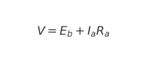
From the electrical side, the total power supplied to the motor is the product of voltage and current. According to the basic equation:
By multiplying this equation by the armature current, we get the total electrical power input:
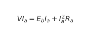
Here, Ia²Ra represents the copper loss in the armature, while EbIa is the mechanical power developed. Since mechanical power is also given by:
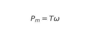
Where T is the developed torque and ω is the angular speed.
By expressing ω in terms of rpm and rps:
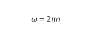
Where n is the speed in revolutions per second (rps) and can also be written as:
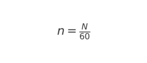
Where N is the speed in revolutions per minute (rpm). Substituting this back into the power equation, we get:
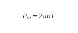
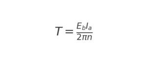
Equating this with EbIa from the earlier equation, we obtain:
2πnT=EbIa
Rearranging for torque:
Since
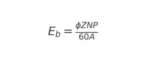
Where ϕ is the flux, Z is the total number of conductors, N is the speed, and A is the number of parallel paths, substituting this into the torque equation gives:
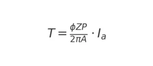
For a given DC motor, the terms ϕZP/2πA are constant, so the torque equation simplifies to:
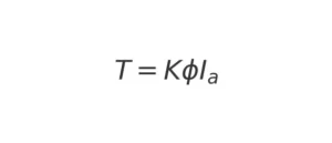
This result shows that the developed torque is directly proportional to the flux and the armature current. Additionally, the direction of this torque depends on the direction of the current in the conductors. If either the flux or current is reversed, the direction of rotation will also reverse. However, if both are reversed, the torque direction remains the same.
In practice, factors like mechanical losses, resistance, and power loss must be accounted for to achieve optimal performance. Balancing these aspects ensures improved motor efficiency and stable rotation.
You can also read difference between AC and DC Voltage.