Introduction
When I first started working with DC motors, I was fascinated by how efficiently they convert electric energy into mechanical motion. These motors are widely used in automotive industries, appliances, and electronics, making them essential devices in our daily lives. Their construction relies on a current-carrying conductor placed inside a magnetic field, generating a force that creates movement. This fundamental principle is described by Lorentz’s Law, which states that a conductor in a field experiences a force, with its direction determined by Fleming’s Left-Hand Rule.
The working of a DC motor is simple yet powerful—it operates using direct current, ensuring efficient torque production for different types of applications. Its unique characteristics make it ideal for tasks requiring precise speed and power control, whether in industrial tools or household appliances. From my experiences handling advanced motor systems, I’ve found that understanding the detailed information about its interaction with circuits helps optimize performance.
What is a DC motor?
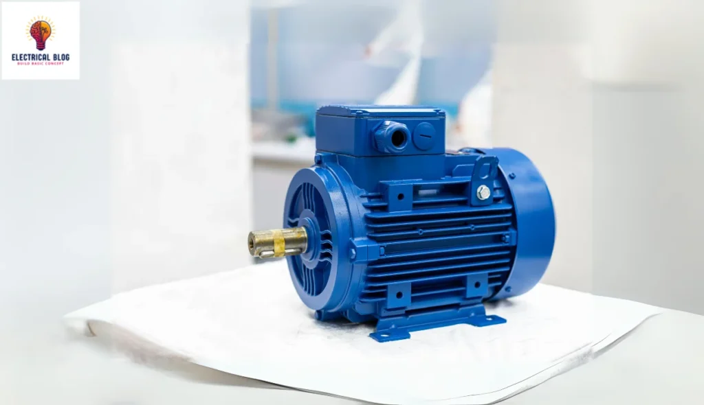
A DC motor is an electrical device that converts electric energy into mechanical motion using direct current (DC). At its core, a rotary component called the armature rests inside the casing, surrounded by strong permanent magnets. When current is applied, the coil generates a magnetic field that interacts with the stationary magnet, producing torque and making the motor rotate. This movement is controlled by a switch known as the commutator, which ensures smooth operation. The full form of a DC motor explains its functionality, as it uses direct current to keep the component running efficiently. Whether in industrial or household applications, this form of motor plays a key role in converting power into motion.
Construction of a DC motor
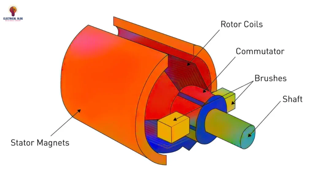
A DC motor is built with several components, each playing a primary function in converting electrical energy into motion. The stator is the stationary part of the motor and consists of a solid outer frame that provides strength and houses various internal parts. The magnetic field inside the motor is generated by the field winding, which is a wound copper wire that carries direct current. The armature is the rotating component, positioned inside the casing and surrounded by magnetic poles. These poles, often made of laminated iron or wrought steel, are fixed in place and help maximize the magnetic flux passing through the gap between the pole shoe and the armature.
The yoke serves as the outer cover and is usually made of cast iron, rolled steel, or silicon steel to ensure low reluctance and strong structural support. The armature core, a drum-like structure, is keyed to the shaft and contains slots to hold the armature windings. These windings, depending on the operating voltages, can be classified as wave winding or lap winding. To prevent eddy current losses, the core is built using laminated materials that allow proper air circulation and cooling.
The commutator, mounted on the shaft, consists of segments made of hard-drawn copper and insulated with mica. Its function is to convert the alternating torque into unidirectional torque for smooth motor operation. Carbon brushes make contact with the commutator, conducting electricity to the armature coils. These brushes are held in place by springs, ensuring continuous electrical connectivity. Every part of the DC motor works together to ensure efficient energy conversion and mechanical performance.

Working Principle of DC Motor
The basic principle of a DC motor is that when a current-carrying conductor is placed in a magnetic field, it experiences a force known as the Lorentz force. This force is responsible for the rotation of the armature, which is a rotating part of the motor made of coils of wire. As current flows through these coils, they create a magnetic field that interacts with the permanent magnets or electromagnets inside the motor. This interaction causes the armature to rotate, and the rotation is then transferred to the output shaft, which can be used for driving a machine, pump, fan, or any other device that requires mechanical work.
Fleming’s Left-Hand Rule
In a DC motor, the movement of the armature is determined by Fleming’s Left Hand Rule, which helps to understand the direction of the force acting on a current-carrying conductor in a magnetic field. If you stretch out your thumb, index finger, and middle finger of your left hand at a 90° angle to each other, each finger represents a different factor.
The index finger shows the direction of the magnetic field, the middle finger represents the current flow, and the thumb indicates the force that moves the conductor. This force is calculated using the formula F = BIl, where B is the magnetic field, I is the current, and l is the length of the conductor. The magnitude of this force is essential in defining the efficiency of a motor’s rotation.
The motor consists of key parts, including the stator, armature, poles, commutators, and brushes, which all play a role in ensuring smooth operation. The armature coil is connected to the power supply, and when current flows through it, a magnetic field is generated. This interaction between the fields of the permanent magnet or electromagnet and the rotating armature creates torque, which causes the rotor to move.
The position of the coils within the motor changes continuously, keeping the rotation consistent. In an actual setup, multiple coils are used to ensure that when one coil is perpendicular to the field and the torque becomes zero, others continue to generate force. This prevents the motor from stopping and allows for continuous motion.
Types of DC Motors
Types of DC motors include:
Self-exciting DC motors
DC Series Motor
DC Shunt Motor
DC Compound Motor
Separately excited DC motors
Permanent magnet DC motors
Self-Excited DC Motors
Self-excited DC motors are a special type of DC motor that generates its own magnetic field using a separate field winding. This winding can be connected in different ways, leading to three types of configurations: shunt, series, and compound. In a series connection, the field winding and armature are in line, while in a parallel setup, they work independently. Some designs use a combination of both to balance efficiency and performance. These motors are widely divided based on their application needs.
DC Shunt Motor
A DC shunt motor is designed for applications where steady speed is required regardless of load changes. Unlike a DC series motor, its field winding is connected in parallel with the armature winding, ensuring that the voltage across both remains the same. This design provides a more stable speed, making it ideal for applications like cranes and hoists, where sudden changes in load could affect performance. The torque produced is nearly proportional to the current, and the motor has low sensitivity to speed variations, ensuring smooth operation.
DC Shunt Motor
A DC shunt motor is widely used in applications where a constant speed is required, regardless of loads. Its field winding is connected in parallel with the armature winding, making the current in both circuits independent of each other. This allows the motor to maintain a stable speed over a wide range of operations. Although its torque is lower at low speeds compared to a DC series motor, it is ideal for devices like fans and pumps that need consistent performance.
DC Compound Motor
A DC compound motor is designed to combine the strengths of both series and shunt motors, providing a balance between high torque at low speeds and constant speed over a wide range of loads. It has field windings that work together to determine the speed-torque characteristics of the motor. This makes it suitable for applications like rolling mills and elevators, where both torque and speed stability are important.

Separately Excited DC Motors
A separately excited DC motor has a dedicated power source for its field winding, which is separate from the one supplying the armature. This design allows for precise control over the magnetic field, leading to better regulation of speed and torque. These motors are typically used in high-performance applications where precision is required, such as industrial automation and specialized machinery.
Permanent Magnet DC Motors
Permanent magnet DC motors are commonly used in applications that require high efficiency and low maintenance. Unlike other DC motors, they do not need an external power source to generate a magnetic field. Instead, permanent magnets are embedded in the motor’s structure, allowing them to operate smoothly. These motors are known for their compact size and are often found in fans, pumps, and servo systems.
Characteristics of DC motors
The performance of a DC motor is determined by key parameters like torque, speed, and efficiency, making it a vital component in electrical machinery. Understanding these characteristics helps in designing highly functional systems for various applications.
Back EMF
When a DC motor starts rotating, the armature moves through the magnetic field of the stator, and according to Faraday’s Law of Electromagnetic Induction, an induced voltage, known as back EMF, is generated. This counter voltage opposes the current flowing through the conductor, following Lenz’s Law. The direction of this EMF is such that it balances the input supply, controlling the speed of the motor.
EMF equation of a DC motor
Eb = ΦNZP / 60A
Where Φ is the flux, N is the RPM, Z is the total conductors, P is the number of poles, and A represents the number of parallel paths in the armature. Understanding this important concept is key to analyzing the characteristics and efficiency of a DC motor.
Torque
In a DC motor, torque is the twisting force that helps in performing work. It is measured in Newton-meters (Nm) and is directly related to current, flux, speed (RPM), and the number of poles (P) in the armature. The torque equation of a DC motor is given by:
Ta = 0.159ΦNZPAIa
Where Φ is the flux, Z is the total conductors, and A represents the parallel paths in the motor. However, not all the torque developed is available at the shaft, as some of it is lost due to frictional losses. The useful shaft torque (Tsh) is given by:
Tsh = 9.55 × output power / N
Speed
The speed of a DC motor is measured in rpm (revolutions per minute) and depends on several factors such as voltage, current, field strength, and armature resistance.
The formula for calculating speed is given by N = K * Eb / ϕ, where K is the proportionality constant, and Eb is the back EMF. The value of K is defined as 60AZP, where A is the number of parallel paths, Z is the number of conductors, and P is the number of poles. The efficiency of the motor, which is the ratio of output power (Pout) to input power (Pin), plays a key role in determining performance.
Applications of DC motors
DC motors are widely used in various fields where precise control, high power, and reliability are required. The application of a DC motor largely depends on the requirements of the equipment and its characteristics. In industries, cranes, lifts, elevators, and winching systems rely on DC motors for their ability to generate high torque at low speeds. Similarly, household appliances like hair dryers, centrifugal pumps, and blowers benefit from their efficiency. Windscreen wipers, fans, and drills also utilize DC motors, providing smooth and consistent performance.
In more advanced applications, handheld tools, heating systems, and cooling systems in aircraft and vehicles require compact DC motors for precision. Computer cooling fans and ventilation systems also rely on DC motor technology. For robotics and automation, 12V DC motors, including 775 DC motors, 555 DC motors, and 5 DC motors, power small yet efficient mechanisms. Toys, starter motors, wheels, and disc drivers use DC motors for seamless operation, while rolling mills, heavy planers, stamping machines, and compressors utilize their high-speed performance in industrial setups.
Conclusion
DC motors play a crucial role in various applications, from industrial equipment like cranes, rolling mills, and compressors to everyday devices such as fans, drills, and toys. Their versatility allows them to be used in vehicles, heating systems, cooling systems, and handheld tools, offering reliable power and efficiency. Whether it’s a 12V DC motor, a 775 DC motor, a 555 DC motor, or a 5 DC motor, each type is designed to meet specific requirements across different fields. With their ability to provide high torque, smooth speed control, and energy efficiency, DC motors continue to be a fundamental part of modern electrical systems.
FAQS
12V DC Motor
A 12V DC motor is a simple, direct current motor that is widely used in applications like scooters, e-bikes, and other mechanical systems. These motors are known for their versatile nature, offering high torque and higher speeds when paired with belts or chains. They are commonly found in DIY projects by hobbyists and inventors due to their low cost and easy usability. Since they are manufactured in large quantities, they remain affordable, but making custom changes can be difficult. Despite this, they are reversible and can be controlled using speed controllers, making them a popular choice for various automation and mobility projects.
775 DC Motor
The 775 DC motor is a multipurpose brushed motor that is commonly used for drilling, cutting, and other mechanical purposes. It is widely found in PCB machines and drill setups due to its high-speed performance. The motor has a shaft diameter of 4.7 mm, a length of 67 mm, and a 16 mm shaft, making it ideal for various applications.