Introduction
The De Sauty Bridge is a simple yet effective tool for measuring an unknown capacitance in a circuit. Paul de Sauty originally invented it to compare a capacitor with a standard one, ensuring a high degree of accuracy. However, the circuit design follows a straightforward principle of null deflection, making it one of the easiest ways to measure pure, non-inductive capacitance.
While widely used, it has a major disadvantage—it struggles with dielectric loss, limiting its practical applications. To counter this, Grover modified the bridge by adding extra resistors, improving its efficiency over a wide range of capacitances. The calculations involved remain simple, making it a valuable tool despite its limitations.
What is De Sauty Bridge?
The De Sauty Bridge is an instrument used to measure an unknown capacitance in a circuit. It follows the principle of null deflection, making it one of the simplest ways to compare two capacitors. The bridge consists of a standard capacitance, two variable resistors, and the unknown capacitor.
A balance point is obtained by varying the resistors, helping to find the capacitance value in terms of a known one. However, for capacitors with dielectric loss, a modified version of the bridge is used. It works on alternating current and provides an effective method for precise calculations.
Working Principle of De Sauty Bridge
The De Sauty Bridge works on the principle of null deflection, meaning no current flows when it reaches a balanced condition. If the potential across the galvanometer is different, the needle moves, indicating an unbalanced condition. To restore balance, the values of variable resistors must be adjusted carefully. This helps obtain an accurate reading by ensuring the voltage drop follows Kirchhoff’s circuital law. When balanced, the sum of voltages across the individual arms of the bridge circuit becomes zero.
According to this application, the potential difference across AB is equal to AD, and across BC is equal to CD. When the bridge is balanced, there is no deflection in the galvanometer, meaning all variable components are set precisely. If the balance is disturbed, varying the resistors allows the bridge to return to its original state. This ensures that the drop in potential in a closed loop follows theoretical expectations. The results of this method make the bridge a reliable tool for electrical analysis. You can also read Torque Equation of a DC Motor.
De Sauty Bridge components
Two Variable Resistors
A variable resistor is a special type of resistor that helps change the value of resistance in a circuit. Its principle is based on altering the length of a resistive track by moving a wiper contact. The position of the wiper determines the effective resistance, controlling voltage and current according to Ohm’s law. This adjustment is crucial for maintaining balance in the bridge when changing conditions need precise tuning.
Galvanometer or detector
A galvanometer is an instrument used to measure electric current in a circuit by detecting small, low currents. It works on the principle of the conservation of energy, converting mechanical motion into electrical signals. The movement of a coil in a magnetic field or a magnetic needle helps indicate the magnitude of the current. It can measure currents as small as microamperes, making it essential for precision. Different types include the tangent galvanometer, mirror galvanometer, and astatic galvanometer, each suited for specific needs.
AC Source
An AC source provides alternating current to the circuit, where the electric current reverses its direction periodically. It changes with respect to time, ensuring a continuous power flow.
Essential Components
The De Sauty Bridge consists of a standard capacitance with a fixed value and an unknown capacitance whose capacitance value needs to be determined. This type of capacitor helps compare a known and unknown component for precise measurements.
Construction of De Sauty Bridge
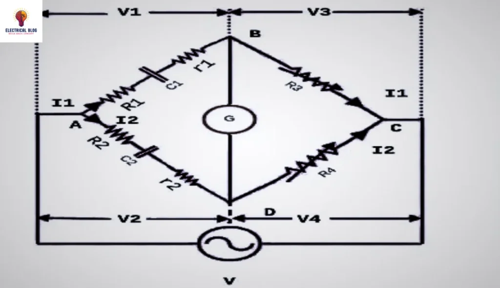
The De Sauty Bridge is built in a quadrilateral shape, where components are placed on its four sides. The standard capacitance (C2) is on AD, while the unknown capacitance (C1) is on AB. Resistors R3 and R4 are on CD and BC, allowing adjustments for the balanced condition.
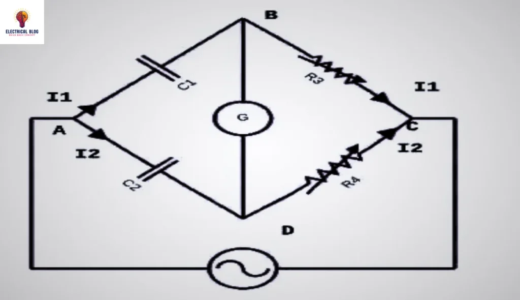
A galvanometer is positioned along one diagonal, while the AC supply is on the other diagonal. The bridge operates independently of frequency, but if capacitors are imperfect or have dielectric losses, balance is never obtained. The values of R3 and R4 must be varied to achieve stability.
De Sauty Bridge Formula
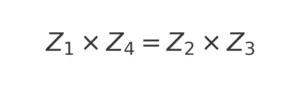
The De Sauty Bridge helps determine an unknown capacitance (C1) by comparing it with a standard capacitance (C2). It consists of variable resistors (R3, R4) and is arranged in four arms: AB, BC, CD, and AD. The balance of the bridge follows the impedance rule.
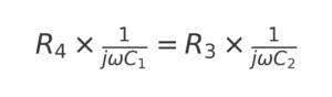
At balance condition, the impedance relation is:
Since impedance for a capacitor is given by jωC, substituting values for each arm, we get:
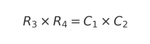
Rearranging,
Solving for C₁,
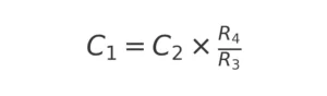
This formula shows how an unknown capacitor can be determined using a balanced condition in the circuit.
Phasor Diagram
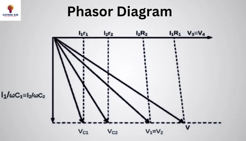
A phasor diagram is a graphical method used to show the directional relationship between alternating quantities in a circuit. In the De Sauty Bridge, the voltage drop across the capacitor (C1) is V1, and across C2 is V2. Similarly, the drop across the resistor (R3) is V3, and across R4 is V4.
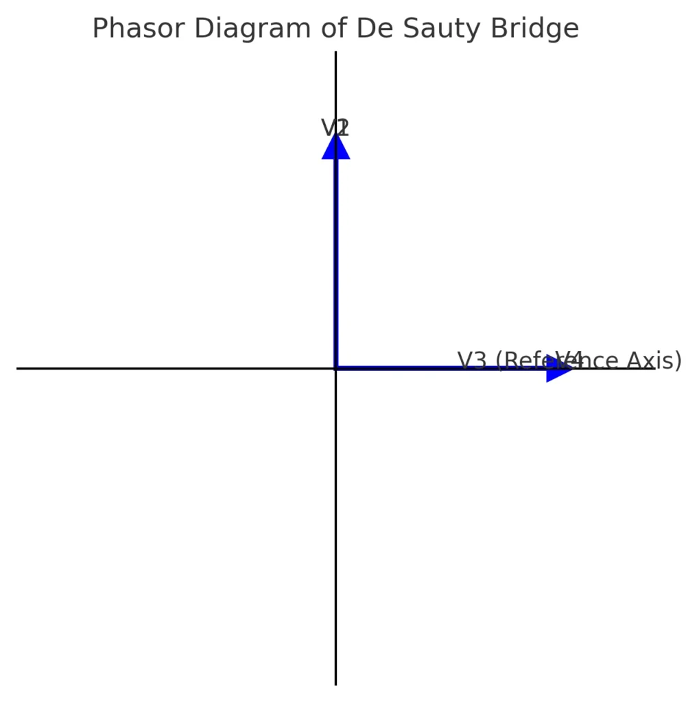
At balance condition, the current through B-D is zero, meaning V1 and V2 are equal to V3 and V4. The reference axis is taken along V3 or V4, with V1 and V2 positioned at a 90-degree angle due to the phase difference in the magnitudes of alternating signals.
Modified De Sauty Bridge
The original version of the De Sauty Bridge could not be used for imperfect capacitors with dielectric loss. Grover modified the bridge to provide accurate results by adding resistors and improving the design. In the modified De Sauty bridge, the capacitors (C1, C2) are connected in series with R1 and R2.
To measure dielectric losses, another set of resistors (r1, r2) helps account for the loss component of each respective capacitor. This ensures that even free capacitors with imperfections can be tested efficiently.
Modified De Sauty Bridge Equation (Step-by-Step Explanation)
To improve the De Sauty Bridge, Grover modified it to work with imperfect capacitors that have dielectric losses. The equations used in the modified bridge help to measure unknown capacitance by considering both resistance and capacitance in the circuit. Below is the step-by-step explanation of the equations.
At balance condition, the impedance relationship in the circuit is:

This equation ensures that the bridge is balanced, meaning the voltage across opposite arms is equal.
The impedance for each arm of the bridge is given as:
For arm AB:

This includes resistance (R1, r1) and capacitive reactance (C1).
For arm AD:

Similarly, this includes resistance (R2, r2) and capacitive reactance (C2).
For arm BC:

The resistance in this arm is R₃.
For arm CD:

The resistance in this arm is R₄.
Substituting these impedance values into the balance equation:
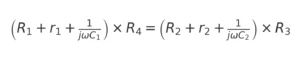
This equation now includes both resistors and capacitors, helping to determine the unknown capacitance.
Breaking this equation into real terms (resistive components) and imaginary terms (capacitive components):
For real terms:

This represents the balance condition for resistive components.
For imaginary terms:


This represents the balance condition for capacitive components.
From the imaginary terms equation:

This final equation allows us to calculate the unknown capacitance (C1) in terms of known resistances and capacitances.
Modified Phasor Diagram
The dissipation factor helps measure energy losses in a capacitor due to resistance. It is given by:

Similarly, for the second capacitor:

These equations represent the relationship between phase angle, capacitance, and resistance in each capacitor.
Using the phasor diagram, we relate resistances and capacitances as follows:

This equation compares the components in the circuit, showing how different parameters influence the capacitor’s behavior.
Multiplying both sides by ω, we get:
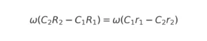
This equation considers the angular frequency’s effect on the capacitor’s losses.
From the balance condition of the modified De Sauty Bridge, we know:

This equation helps in estimating unknown capacitance using known parameters.
Finally, the equation for the dissipation factor difference is:
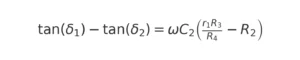
This equation is useful when comparing different capacitors.
Key Understanding
The phasor diagram visually represents the relationship between capacitance, resistance, and phase angle.
The dissipation factor helps quantify energy losses in capacitors.
The final equation allows for estimating the dissipation factor of an unknown capacitor if one is already known.
Advantages and Disadvantages of De Sauty Bridge
Advantages
The De Sauty Bridge has a simple circuit design, making it easy to use.
It helps to obtain the balance condition quickly with minimal effort.
It provides precision and correct values when used with air capacitors.
The instrument allows users to compare capacitors accurately.
It does not require complex adjustments and avoids various factors affecting measurements.
Disadvantages
It can be used only for air capacitors and does not work with imperfect capacitors.
If the capacitors are not free from dielectric loss, the balance condition is not possible to achieve.
The accuracy can be disrupted by stray capacitance and the internal resistance of the AC source.
The process of measuring some capacitors can be time-consuming.
The bridge may fail to provide correct values when dealing with practical limitations.
Applications of De Sauty Bridge
The De Sauty Bridge is widely used for measuring unknown capacitance in circuits with high precision and accuracy.
It helps in detecting dielectric loss in capacitors, making it useful for laboratory applications.
Engineers use it to analyze impedance, including reactance and resistance, in electrical circuits.
It is applied in engineering applications, especially in power systems and electrical machines.
The bridge is useful for comparing a standard capacitance with an unknown one to obtain precise values.
Conclusion
The De Sauty Bridge is an essential instrument in electrical engineering that helps measure unknown capacitance with high accuracy. Its simple circuit design and uncomplicated calculations make it easy to use in various bridge circuits. The advantage of this AC bridge is its ability to compare capacitors effectively.
However, the disadvantage is that it can only find values of capacitors that are free from dielectric loss. To overcome this, a modified version of the bridge is used for more precise results. With the right components, it remains a reliable tool for analyzing an electrical circuit.