Introduction
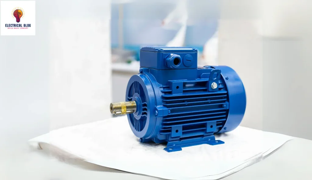
A stepper motor is a versatile and precise motion control device that moves incrementally rather than continuously. Unlike DC motors, it operates using digital pulses, turning the motor’s shaft by fixed degrees for precise rotation. The electromagnetic field inside the motor generates a rotating force, ensuring smooth and controlled movement. Due to its accuracy, it is widely used in industrial applications where precision matters.
The working principle of a step motor is based on electromagnetic induction, where a brushless electric system creates movement. Its construction allows for reliable operation in complex systems, making it ideal for automation. Different types of stepper motors offer unique advantages, providing a comprehensive understanding of their use. With their simplicity and controlled motion, these motors play a key role in many industrial sectors.
What is a stepper motor?
A stepper motor is a synchronous electromechanical device that divides a full rotation into equal steps for precise control. It operates using a stator and rotor, where the winding is split into phases—often two or more. Each step is triggered by energizing the stator in a specific sequence, causing the rotor to align with the nearest pole.
The step angle determines how much angular movement occurs per pulse, with a typical value of 1.8 degrees, making 200 steps per full rotation. The speed and distance the shaft moves are proportional to the rate of digital pulses applied. Stepper motors are available in various NEMA sizes, such as NEMA 17, 23, and 24, which refer to their frame diameter in inches.
A key advantage is their ability to hold a position even without power, making them ideal for open-loop systems like CNC machines. Their permanent magnets ensure reliable movement and precise frame alignment. Because of this, NEMA motors are widely used in automation and precision-based applications. You cann also read single-phase induction motor.
Stepper Moter diagram
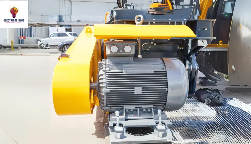
Stepper Motors
How a stepper motor works
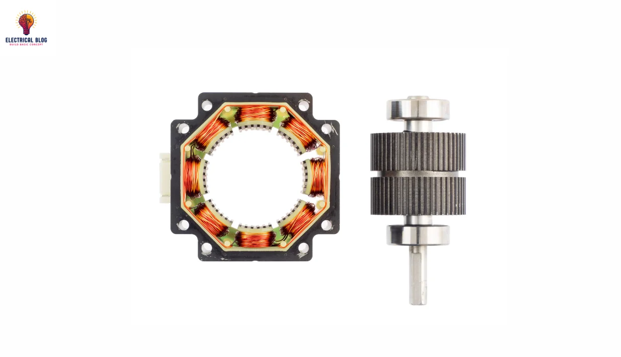
The working principle of a stepper motor is based on precise rotation using an inner rotor and a stationary stator. The stator is an outer cylinder containing electromagnets arranged into groups called phases. The rotor, an inner shaft, has permanent magnets or pole pieces that align with the electromagnets.
Each phase is energized in a specific sequence, making the rotor rotate in steps. When the first phase is activated, the rotor moves slightly, and when the second is powered, it continues the motion. By repeating this sequence, the direction of rotation and position can be controlled with high accuracy.
A higher number of steps per pulse results in smaller angular rotation per step, improving position resolution. This allows precise motion in automation systems, making stepper motors ideal for controlled movement in various devices that require step-based adjustments. You can also read single-phase motor.
Understanding Step Angle in Stepper Motors
The step angle of a stepper motor determines its angular rotation per pulse based on the input signal. A standard step angle typically varies between 1.8° and 0.9°, with a smaller angle providing better positional accuracy. A higher number of steps per revolution improves precision, making it ideal for detailed movements.
A common setting of 1.8° results in 200 steps/revolution, while 0.9° offers 400 steps/revolution for finer control. Advanced microstepping techniques allow for less than 1° movements, making them suitable for high-precision applications. These features help stepper motors achieve smooth and accurate positioning in automation and robotics.
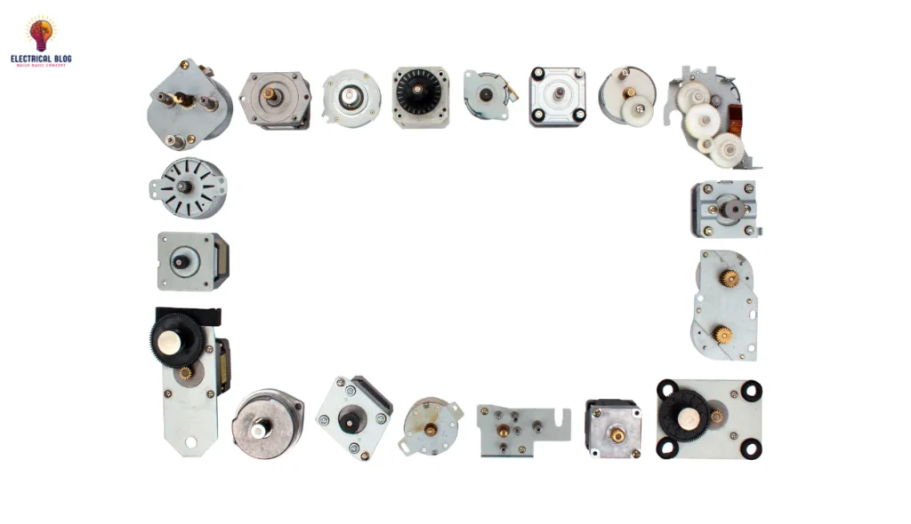
Stepper Motor Types
Variable Reluctance Stepper Motor
Permanent Magnet Stepper Motor
Hybrid Stepper Motor
Variable Reluctance Stepper Motor
VR stepper motors use a rotor with soft iron teeth and a stator with only electromagnets. They operate on the principle of minimum magnetic reluctance, where the rotor teeth align with the stator poles when powered. As the next electromagnet is activated and the first is turned off, the rotor rotates slightly, producing a controlled step motion.
This design is simpler and has a less efficient construction when compared to permanent magnet types. However, its windings and precise alignment ensure smooth rotation when energized. The ability to control movement accurately makes it useful in applications that do not require extreme precision.
One of its key advantages is its simple build, leading to low manufacturing costs while still delivering high torque output. Its compact size makes it suitable for systems needing moderate power, making it ideal for applications requiring moderate precision without complex controllers.
Permanent Magnet Stepper Motor
PM stepper motors use strong magnets in the rotor, while the stator has only electromagnets. When a phase is powered, the rotor aligns with the nearest stator pole, ensuring smooth movement. This design generates higher torque compared to variable reluctance-type motors, making them ideal for applications that require stability.
These motors are more efficient and provide precise stepping, but the rotor magnets can increase the overall cost. Their construction includes windings and a carefully designed feature that enhances performance. The interaction between the magnetic fields creates rotational motion, ensuring steady and controlled movement.
A key advantage of PM stepper motors is their higher efficiency and torque when compared to VR motors. They offer precise positioning and control while using lower power consumption. This balance of efficiency and accuracy makes them suitable for applications that need reliability without excessive energy use.
Hybrid Stepper Motor (Combination of VR and PM types)
Hybrid stepper motors combine the best features of PM and VR designs to deliver high performance in a small form factor. Their rotor includes soft-iron teeth along with permanent magnet segments, which improve precision and efficiency. The use of magnets ensures high torque, while the wide polar arc and salient rotor poles allow for smoother movement. This construction helps integrate key elements from both PM designs and VR technology, making them more reliable.
One of the main advantages of hybrid stepper motors is their enhanced torque output with a reduced step size for smoother motion. Their reasonable cost makes them suitable for a wide range of applications, including CNC machines and 3D printers. Their toothed stator poles help in precise positioning, which is essential for automation. Due to their superior design, hybrid stepper motors are widely used where both power and accuracy are required.
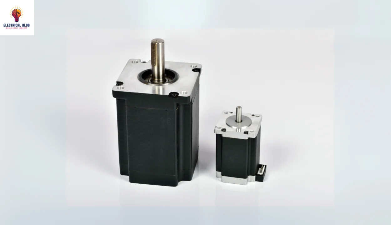
Stepper Motors
Driving techniques
A stepper motor requires special circuits due to its complex design, and different driving techniques are used to control its movement. One example is the four-phase system, where different methods are applied to move the rotor efficiently. Some of these techniques include single excitation mode, full-step drive, half-step drive, and microstepping. Each technique has its advantages depending on the application and precision required.
Single excitation mode
The single excitation mode is a basic method that was used in older systems but is not used much today. In this technique, each phase of the stator is triggered alternatively, causing it to magnetize and demagnetize to move the rotor forward. This method is simple but lacks precision and efficiency, making it less common in modern applications. However, it is still important to understand its working principle.
Full-step drive
The full step drive method improves performance by activating two stators at the same time within a shorter time period. This technique allows the stepper motor to generate high torque, making it suitable for high-load applications. Since both stators work together, the motor moves more forcefully, ensuring better power delivery in demanding systems.
Half-step drive
The half-step drive is related to the full-step drive but provides better control. The stators are arranged next to each other, and the first two stators are activated first, followed by the third. This cycle of switching between them results in improved resolution while decreasing torque slightly. It offers a balance between power and smooth motion, making it useful in many applications.
Micro stepping
Microstepping is the most frequently used technique because of its accuracy and smooth operation. It works by supplying a variable step current through a stepper motor driver circuit to the stator coils in a sinusoidal waveform. The small step current enhances precision and is extensively used in applications that require high accuracy. Additionally, it helps decrease operating noise to a large extent, making it ideal for sensitive systems.
Types of Wiring
Stepper motors use different wiring configurations based on whether they are two-phase unipolar or bipolar motors. A unipolar motor has windings with a center-tapped common lead, allowing easy switching of the current flow. It typically has 5 to 8 leads, where a five-lead or six-lead setup allows only series connection, while an 8-lead version supports both series and parallel connections for flexible operation.
A bipolar stepper motor has a single winding per pole, requiring the direction of supply to change through the driving circuit. This makes its operation more complex, unlike the bifilar motors used in unipolar configurations. The construction of a bipolar motor ensures better performance but demands precise reversing of the current flow. In contrast, unipolar motors simplify control but may have efficiency trade-offs.
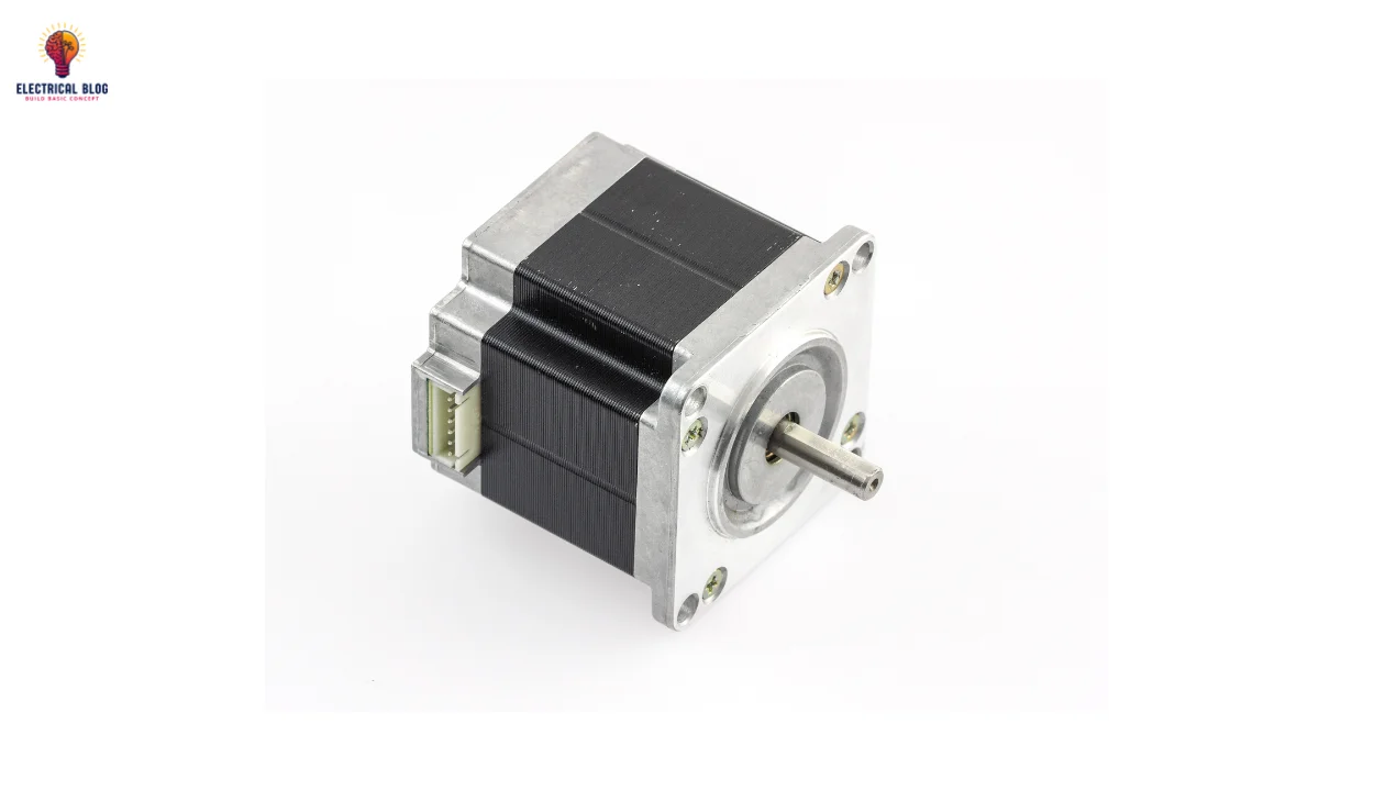
Stepper Motors
Stepper Motor Interfacing with the 8051 Microcontroller
Stepper motor interfacing with the 8051 is simple and can be done using three modes: wave drive, full step drive, and half step drive. The motor operates by switching between 0 and 1 on the motor’s four wires, selecting a suitable drive mode for running the motor. Additionally, two wires must be coupled to a voltage supply to complete the circuit. A unipolar stepper motor is commonly used in such setups due to its simplicity.
The four ends of the coils connect to the primary four pins of port 2 on the microcontroller, while the ULN2003A serves as a current driver IC. Since the microcontroller cannot provide enough power, the ULN2003A is used, which contains a collection of seven pairs of NPN Darlington transistors. The design of a Darlington pair involves two bipolar transistors working together to achieve maximum current amplification and improve motor performance.
The driver IC has input pins (7) and output pins (7), along with dedicated power supply and ground terminals. Typically, 4 input and 4 output pins are utilized in this interfacing. As an alternative, the L293D IC can also be used for amplification when higher power is required. Proper wiring and connection of components are essential to ensure smooth motor operation.
It is important to observe the common wires and the four coil wires carefully using a multimeter to check resistance readings. If the two phases are in equal phase, the similar resistance should be observed. The two coils with the same finish points will show double resistance compared to the common point and a single endpoint. Proper wiring is critical to ensure the stepper motor turns efficiently and functions as expected.
Advantages of Stepper Motors
Precise positioning is achieved, whether for full rotation or partial rotation, making stepper motors ideal for detailed movements.
High resolution ensures excellent speed and position control, especially in open-loop systems that do not require feedback devices.
The ability to start, stop, and operate smoothly at a constant angular velocity provides a high degree of precision.
Stepper motors can hold position efficiently even without power, thanks to their highly detented nature.
Easy control using pulses allows for simpler programming, making it more accessible for automation projects.
Less maintenance is needed since stepper motors have no brushes, reducing wear and tear over time.
They are suitable for applications like CNC machines, where positions must be accurately controlled for high-precision tasks.
Disadvantages of Stepper Motors
Stepper motors produce less torque compared to brushed DC motors of a similar size, making them less powerful in high-load applications.
Vibration and resonance are likely to occur if the motor is not designed properly, which can affect smooth operation.
Stepper motors require a driver circuit to function properly, which increases costs and adds complexity to the system.
Feedback devices may be required in applications that need a high level of precision for accurate movement.
Speed variations can happen at higher output speeds due to limitations in response time, making them less effective in fast-moving systems.
Applications of stepper motors
CNC machines like routers, lathes, and mills use stepper motors for precise movement and cutting operations.
3D printers rely on stepper motors to control the movement of the print head for accurate layering.
Peripheral equipment such as scanners, printers, plotters, tape drives, and CD/DVD drives uses stepper motors for controlled motion.
Industrial robotics and material handling systems utilize stepper motors for smooth and efficient positioning.
Wafer handling equipment is used in the semiconductor industry to move delicate wafers with high precision.
Medical equipment, like blood analyzers and imaging equipment, depends on stepper motors for accurate testing and diagnostics.
Automated production machinery, including labeling machines, ensures precise control during manufacturing processes.
Scientific instruments such as spectroscopy equipment require stepper motors for detailed measurements and experiments.
CCTV camera systems use stepper motors for focus, zoom, and lens control, while radio-controlled vehicles, quadcopters, and cranes need them for positioning adjustments.
Troubleshooting
Troubleshooting is the process of checking the motor status to determine if the stepper motor is working or not. A checklist helps to troubleshoot the issue effectively.
First, verify the connections, code, and circuit to ensure they are properly configured. If they are incorrect, the motor may vibrate but not rotate.
If the motor is still not working, check the voltage supply. Without proper power, it will fail to operate or will only shake in place.
Examine the endpoints of the four-coil system that is allied with the ULN2003A IC. Discover the two general endpoints and connect them to a 12 V supply.
If the motor does not start, try adjusting the residual four wires connected to IC ULN2003A. Attempt different possible combinations to find the proper wiring; otherwise, the motor will vibrate in place instead of revolving.
Difference between Stepper Motor and Servo Motor
| Feature | Stepper Motor | Servo Motor |
|---|---|---|
| Control System | Open loop control, position is calculated using step counts. | Closed loop control with feedback for higher accuracy. |
| Power Consumption | Holds position without power when not moving. | Requires continuous power to maintain position using feedback. |
| Accuracy and Speed | Less accurate at high speeds due to delay between pulses. | More accurate at all speeds due to feedback control. |
| Movement Type | Moves in discrete steps, making a full rotation in increments. | Can rotate continuously to any position smoothly. |
| Driver Complexity | Uses a less complex driver for basic operations. | Require more complex drivers, often including an amplifier. |
| Applications | Common in printers, scanners, and CNC machines. | Found in robotics, industrial automation, and 3D printers. |
Conclusion
Stepper motors are widely used in various applications due to their precise positioning, discrete steps, and open-loop control. They are ideal for CNC machines, printers, and automation systems where controlled movement is required. However, they may experience vibration, resonance, and less accuracy at high speeds, making them unsuitable for some tasks.
Compared to servo motors, stepper motors operate with less complex drivers, hold position without power, and are simpler to control. On the other hand, servo motors provide higher accuracy, feedback control, and smooth continuous rotation, making them preferred for robotics and industrial automation. Choosing between these motors depends on the application’s requirements for precision, speed, and control complexity.