Introduction
During my early days working with digital systems, I often came across devices that needed a steady signal. One such vital electronic component is the local oscillator, a simple yet powerful tool that converts DC supply into an oscillating AC wave. It plays a critical role in generating frequency-based outputs that are essential for everything from computers to crystal radios.
This article discusses how a local oscillator is used in a range of applications, whether mechanical or electronic, like RC, tuned, and harmonic oscillators. One might find it in complex circuit designs or embedded in digital generators, where timing is a key requirement. I’ve seen firsthand how applicable these types of oscillators are, even in simple setups, adapting to varied working conditions and performance needs.
What is a local oscillator?
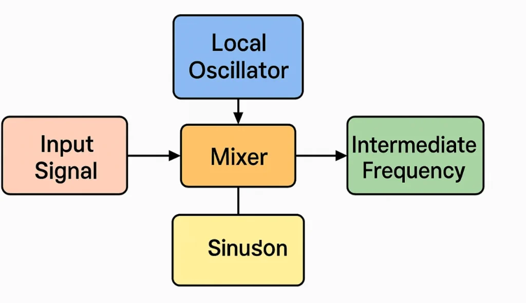
Local oscillators are a specific type of oscillator used to support frequency conversion by producing a sinusoidal signal that combines with the input signal via a mixer. The process that is being described here is known as heterodyning, and it involves the production of the sum and difference of the oscillator’s and input frequencies.
This method is known for its accurate detection and efficient function in generating the resulting intermediate frequency from a single stage. I’ve worked on designs where the mixer and oscillator are combined within one block, which helps with the reduction of power, cost, and space. The final audio output becomes much easier to amplify and tune using this smart modification approach. You can also read about Step Recovery Diode.
Local Oscillator Working Principle
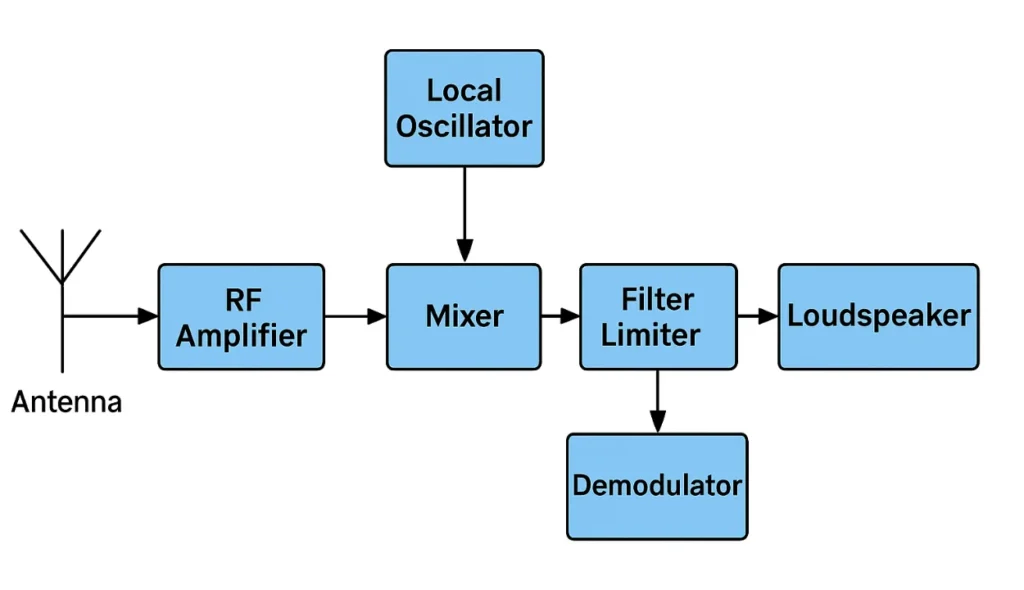
In my earlier days troubleshooting a radio receiver, I saw how the antenna caught signals that were then passed to the RF amplifier. This is where the unwanted parts get removed, and only the tuned signal goes forward. It is possible for this signal to combine with a frequency that is produced by a local oscillator via the use of the superheterodyne technique.
This mixing happens in the mixer, producing an IF (intermediate frequency), which is easier to handle than the original carrier wave. The frequency is now more suitable for further processing and can be compared across channels. From here, the IF signal is amplified, cleaned through a filter, and then stabilized using a limiter so that the level is maintained.
That filtered signal is fed to a demodulator, often known as a detector, where it is demodulated into an audio form. I’ve worked with systems that allowed switching between different demodulators to choose the preferred output depending on use. This is how even complex FM signals get converted into clear sound.
Lastly, the signal is brought to life by passing through a loudspeaker, which is the last step in the signal’s trip from the source. Thanks to this designed structure, especially the fixed and well-processed filtering, every particular channel’s output becomes clear. I even came across one project via PCBWay where this entire flow was neatly laid out on a custom board. You can also read about Bipolar Junction Transistor.
Local Oscillator Circuit Diagram
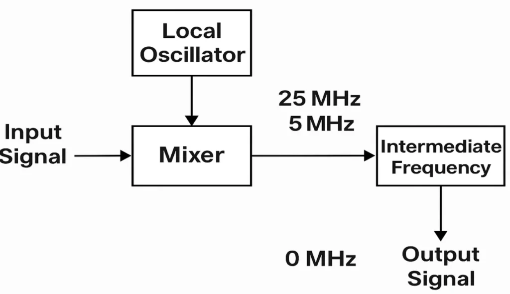
In the superheterodyne receiver, a local oscillator is part of the main circuit that helps to generate a new frequency by mixing an input signal with a separate carrier wave. The principle of heterodyne, which is regulated by trigonometric rules, is followed by this procedure throughout its whole process. When I first built one in my workshop, the way it produced beats using different frequencies amazed me.
For instance, if you input a 10MHz signal and mix it with a 15MHz oscillator, the output (o/p) will give you two beats: a higher one at 25MhHz and a lower one at 5MHz. This variation in frequencies makes the signal easier to filter and amplify, and I’ve seen this work even in complex electronic devices. The IF signal that comes out can then be processed through filters and amplifiers to get clean output.
The tuning of the oscillator is key—it helps identify the right signal and lets the system permit only the desired one to pass. This changing of oscillator frequency ensures we catch the right channel, again and again. Every time I tested it, I found it surprisingly easy to adjust and refine, making it one of the most reliable techniques known in RF systems. You can also read about Bipolar Junction Transistor.
Classification of Oscillators
Linear Oscillator
In my experience designing linear circuits, the most well-known types are LC and RC oscillator systems that generate stable, periodic waveform outputs. The LC models like Colpitts and Hartley use a resonant circuit formed by an inductor and capacitor, either in a capacitive or inductive divider setup. By adjusting the value of these parts, we can fine-tune the frequency to meet precise needs. This is particularly suitable for applications needing accurate control over frequency and output.
The RC Phase Shift oscillator uses a combination of resistor and capacitor elements to create intentional delays that sum to 360 degrees. Once aligned, this setup gives a clean sine wave, which is highly valuable for testing and audio designs. An operator is responsible for configuring the network in such a way that it achieves the desired characteristics and maximum stability. I have personally had to adjust voltage conditions to make sure the feedback loop functions properly.
Relaxation Oscillator
From my hands-on work with digital systems, I often used relaxation oscillator circuits to create non-sinusoidal waveforms like square and sawtooth waves. These are highly versatile and widely used in timing functions where predictable output is key. Their success depends on stable frequency, proper configuration, and responsive switching behavior.
The UJT (Unijunction Transistor) and 555 Timer are popular examples that rely on bias voltage, threshold, and discharge capacitors to operate correctly. Technicians can adjust resistors, settings, and parameters to modify the duty cycle, tailoring the signal to suit various applications. I’ve often adapted these devices because of their flexible characteristics and ease of control over output waveform design.
Why Use a Local Oscillator?
A local oscillator helps convert high-frequency signals into intermediate ones, making them more manageable. This simplifies the receiver architecture, lowers costs, and makes the system more user-friendly. In my experience, this has greatly improved reliability and reduced maintenance and repairs.
It allows the use of filters and amplifier stages that are tailored to narrow bands, which enhance performance. These setups are efficient at eliminating noise and improving accuracy, even in closely spaced frequencies. The processing becomes more precise, which is key when working with weaker signals.
With better selectivity, the system can distinguish and isolate the desired signal from a crowded frequency range. I’ve seen how technicians benefit from the predictable processing, making tuning easier for all users. This results in noticeable improvements in amplification, adjustments, and overall device accuracy.
Advantages of Using a Local Oscillator
A local oscillator helps by converting high-frequency signals into intermediate frequency (IF), which simplifies the processing. It allows the use of fine-tuned filters and amplifier stages for narrow ranges, leading to better quality and less noise. I’ve seen operators easily isolate desired signals, even in complex real-world scenarios, with greater efficiency.
In portable devices like cell phones or monitoring systems, integrating the oscillator and mixer cuts costs and reduces power use. These circuits are simpler, with fewer components, and are easier to build during assembly and manufacturing. This improves battery life, boosts reliability, and keeps performance strong in power-limited environments.
Application of Local Oscillator
In television boxes, a local oscillator helps select the user-selected channel by converting it into an intermediate frequency for smoother processing. This improves fidelity and ensures stable reception with less interference. I’ve calibrated many such boxes for clients to keep their viewing crystal clear.
Modems rely on oscillators to decode Internet data and match it to the correct standard. The operator sets the oscillator to the required frequency, keeping performance and efficiency high. Even with minimal errors, good tuning makes a big difference.
In microwave relay systems, oscillators handle conversions and retransmission of received signals over long distances. I’ve used them to maintain reliability in remote environments where stable frequencies are critical. The system must also operate stably under varying conditions.
For radio telescopes, especially those studying deep space, oscillator accuracy affects the quality of cosmic observations. Technicians often fine-tune the oscillator to amplify weak signals coming from light-years away. The smallest drift can throw off the entire readout.
Atomic clocks use oscillators to generate a precise and accurate timing signal. Even tiny adjustments in the oscillator affect time calibration, so operators regularly perform monitoring. In critical aerospace applications, this level of control is non-negotiable.
In military countermeasures, oscillators are used to generate jamming signals and decode enemy transmissions. The knowledge and technical skills needed here are advanced. It’s about balancing safety, performance, and strategic advantage.
Whether in telecommunications, aircraft, or ground systems, I’ve seen oscillators prove essential for modulation, conversion, and high-efficiency signal operations. With every tuning, these tools unlock real-world functionality in diverse and demanding setups.
Conclusion
After analyzing its mechanism and working, it is clear that the local oscillator plays a key role in modern communication systems. Whether in cable TV, radio, or telemetry, it ensures efficient and stable signal processing across a wide range of applications.
It not only simplifies design but also reduces costs and energy consumption, which boost overall performance. With ongoing technological advancements, we can expect new innovations that further optimize functions and support the development of future wireless technology.
I’ve seen firsthand how precise oscillator setups elevate system reliability in high-demand scenarios, including telescope operations with tight requirements. This steady flow of progress will surely carry us forward.