Introduction
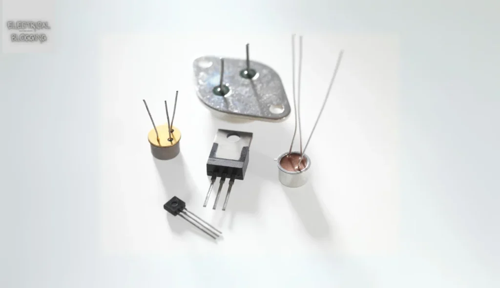
When working with electrical circuits, understanding transistors like BJT and FET is crucial. The acronym BJT stands for Bipolar Junction Transistor, while FET means Field Effect Transistor. Both devices are used in electronics for switches and amplifiers, each with unique control characteristics.
A major difference lies in how charge carriers move; BJTs allow both majority and minority carriers, while FETs use only majority. Factors like current, voltage, frequency, and power ratings influence their operating performance. Available in various packages, these transistors provide precise control for different types of work in electrical applications. In this article, we will cover key difference between BJT and FET.
What is a BJT?
A BJT is a transistor that uses both majority and minority carriers to manage current flow. It comes in two types, PNP and NPN, making it suitable for amplifiers, switches, and other electronic applications. From TVs and computers to mobile phones and audio systems, BJTs are widely used in industrial control and radio transmitters. These semiconductor devices efficiently handle charge movement to enhance circuit performance. you can also read difference between wavelength and frequency.
Construction of BJT
A BJT is a bipolar transistor that comprises two p-n junctions in its structure. It is classified into two types, PNP and NPN, based on how the semiconductors are placed. In NPN, a lightly doped P-type layer sits between two heavily doped N-type layers, while PNP is the opposite. These terminals are named emitter, base, and collector, labeled as E, B, and C.
When a high voltage is applied in reverse mode, a strong electric field forms across the BE junction. This field stops the flow of electrons from the B-terminal to the collector, creating a huge region with no current. In forward mode, the emitter sends electrons toward the base, where some recombine with holes while others overflow to the collector. This process generates a controlled current.
The potential difference across the BE junction determines if electrons can enter the collector. If it’s too small, no current flows. This property makes the BJT useful as a switch. In PNP, the principle is similar, but the majority of charge carriers are holes, and the direction of flow is reversed. This clever design makes BJTs effective for various electronic applications.
Regions of BJTs
A BJT operates in three regions: active, cut-off, and saturation. In the active region, the transistor is ON, and the collector current is controlled by the base current (IB) following the formula IC = βIC. It works as an amplifier here and is insensitive to VCE changes.
In the cut-off region, the transistor is OFF, so no current flows between terminals like the emitter and collector. The saturation region has extremely less VCE, where the collector current mainly depends on VCE rather than IB, with minimal changes in current flow.
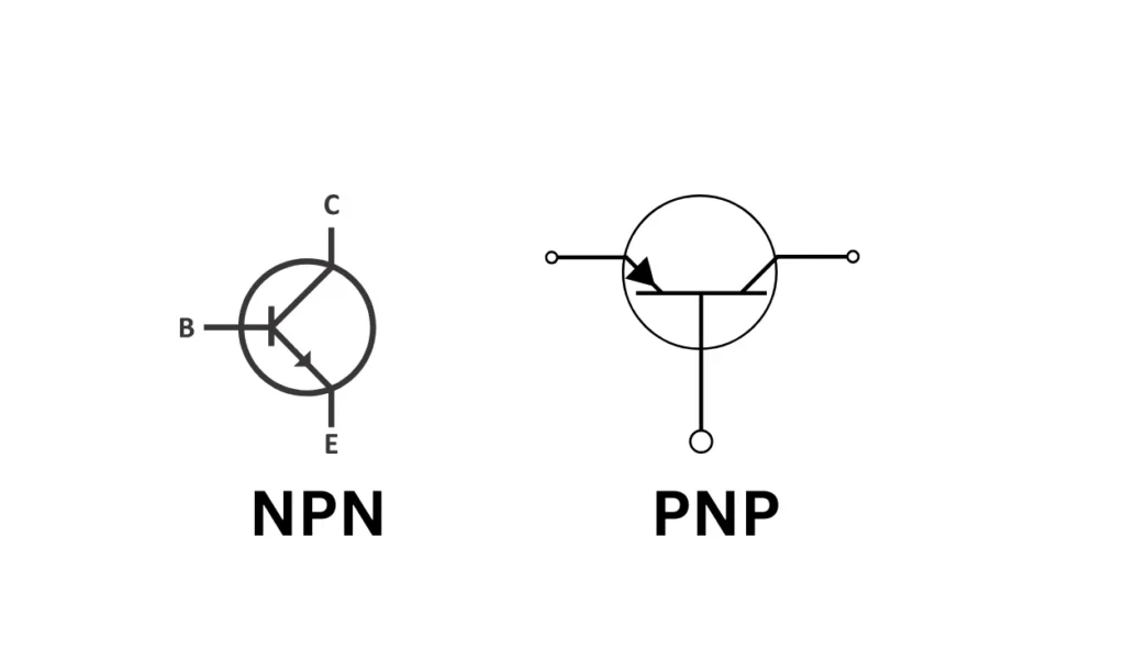
Types of BJTs: NPN and PNP transistors
There are two types of BJTs based on the arrangement of their semiconductor layers:
NPN Transistor: An NPN transistor has a p-type middle layer (base). The collector and emitter are n-type. Current flows from the collector to the emitter, and it is controlled by the current at the base.
PNP Transistor: A PNP transistor has an n-type middle layer. The collector and emitter are p-type. Here, current flows from the emitter to the collector. The base current controls this flow.
Key Characteristics of BJTs
Current Amplification:
A Bipolar Junction Transistor (BJT) amplifies current. A much bigger collector current is regulated by the tiny base current. This allows for significant amplification in analog circuits. This feature is essential for applications where signal boosting is needed.
Saturation and Cut-off Modes
In saturation mode, the BJT is fully “on.” Current flows freely between the collector and emitter. In contrast, in the cut-off mode, the transistor is fully “off,” and no current flows. These two modes are crucial for switching applications. Here, the BJT acts as an electronic switch.
Input-Output Characteristics
The input characteristics of a BJT are like those of a forward-biased diode. The output characteristics depend on the transistor’s operating mode: active, saturation, or cut-off. These characteristics help define the voltage-current relationships in circuit design.
What is FET?
A FET is a unipolar transistor that is quite dissimilar from a BJT in design and function. It consists of three terminals: source, drain, and gate, where electric fields play a key role. The output current is controlled by the voltage applied across the source and gate terminals.
In a FET, charge carriers such as electrons or holes flow from the source to the drain through an active channel. This design makes FETs useful for precise current control, setting them apart as a unique type of transistor in electronics.
Construction of FET
The field-effect transistor is classified into two types: JFET and MOSFET, both sharing similar principles. In a p-channel JFET, majority carriers like charges flow from the source (S) to the drain (D) through a conductive channel.
The gate terminal is connected in reverse bias mode with a voltage source, forming a depletion layer. As this voltage is increased, the depletion layer grows, helping to stop or control the current flow by changing the charge movement through the regions of the FET.
Regions of FET
FETs operate in three regions: cut-off, active, and Ohmic. In the cut-off region, the transistor is OFF, with no conduction between the source and drain when VGS is higher than VGS,off. In this state, ID = 0.
In the active (or saturation) region, the transistor is ON, and the drain current is controlled by the gate-source voltage while being less sensitive to V_DS. The equation is:
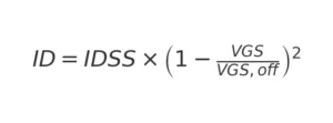
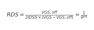
In the Ohmic region, the transistor behaves like a VCR (voltage-controlled resistor) where ID is comparable to the source-drain voltage. The equation is:
Types of FETs: JFET and MOSFET
JFET (Junction Field Effect Transistor): A JFET uses a reverse-biased junction to control current. It is a simpler version of FETs. It works by using the gate voltage to restrict the channel’s conductivity.
MOSFET (Metal-Oxide-Semiconductor Field Effect Transistor): The MOSFET is a better FET. It has an insulated gate. It offers higher performance and lower power usage. It comes in enhancement and depletion modes to control the channel.
Key Characteristics of FETs
Voltage-Controlled Operation
One of the defining features of Field Effect Transistors (FETs) is that they are voltage-controlled devices. Unlike Bipolar Junction Transistors (BJTs), which are current-controlled, FETs are not. They control the current flow between the source and drain terminals. This is based on the voltage at the gate. FETs can regulate current with a small voltage. This makes them efficient in amplifiers and switches.
High Input Impedance
FETs have a very high input impedance, typically in the range of megaohms or higher. This means that very little current is drawn from the signal source. So, FETs are ideal for circuits where minimizing power loss is essential. The high input impedance reduces the loading effect on earlier circuits. This helps maintain signal integrity.
Different Modes
Depletion and enhancement FETs can operate in two distinct modes: depletion and enhancement.
In depletion mode, the FET conducts with no gate voltage. A voltage reduces the current flow.
In enhancement mode, the FET stays off until a voltage is applied. This enhances the channel and allows current to flow. The two modes make FETs flexible. They suit many uses, from power switching to signal amplification.
Difference between BJT and FET
| Aspect | BJT | FET |
|---|---|---|
| Full Form | Bipolar Junction Transistor | Field Effect Transistor |
| Component Type | Bipolar component | Uni-junction component |
| Terminals | Base, Emitter, Collector | Gate, Source, Drain |
| Charge Carriers | Uses majority and minority carriers | Uses only majority carriers |
| Input Impedance | Low (ranges from 1K to 3K) | Large input impedance |
| Control Type | Current controlled | Voltage controlled |
| Noise | More noise | Less noise |
| Frequency Response | Affected by frequency changes | High frequency response |
| Temperature Stability | Less stable, depends on temperature | Better stability against heat |
| Cost | Low cost | Expensive |
| Size | Larger in size | Smaller in size |
| Offset Voltage | Has offset voltage | No offset voltage |
| Gain | More voltage gain, less current gain | Less voltage gain, more current gain |
| Switching Speed | Medium switching time | Fast switching time |
| Biasing | Simple biasing | Difficult biasing |
| Power Consumption | Consumes more power | Consumes less power |
| Applications | Suitable for low-current applications | Suitable for low-voltage applications |
| Coefficient Type | Has a negative temperature coefficient | Has a positive temperature coefficient |
| Voltage Gain | High voltage gain | Low voltage gain |
| Output Impedance | High output impedance due to gain | Low output impedance |
| Conduction Control | Conducts via positive terminals like base | Conducts via negative gate terminal |
| Performance | Performance is affected by frequency | Performance is stable due to high response |
| Switching Efficiency | Medium switching efficiency | Fast switching efficiency |
BJT vs FET: Key Difference Between BJT and FET
- The BJT (Bipolar Junction Transistor) is a current-controlled device. The collector-emitter current is regulated by the base current. In contrast, the FET (Field Effect Transistor) is a voltage-controlled device. A voltage on the gate regulates the current between the source and drain.
- BJTs usually have a low input impedance. So, they draw more current from the input signal. On the other hand, FETs have a high input impedance. This reduces the current drawn and minimizes power loss.
- BJTs tend to have higher power consumption because of their current-controlled nature. In contrast, FETs consume less power, making them ideal for low-power applications.
- The FET is preferred for high-speed switching. It switches faster than the BJT, which is slower.
- FETs are more thermally stable than BJTs. They have no minority carriers. This makes FETs better in high-temperature environments. BJTs can be less stable under thermal stress.
- BJTs are common in amplification circuits. They can amplify small current signals. FETs are widely used for switching, especially in high-frequency applications.
Applications
Common Applications of BJTs
BJTs (Bipolar Junction Transistors) are common in audio amplifiers. They can handle high gain and drive current efficiently. This makes them ideal for low-noise, high-gain amplification in audio systems. Also, BJTs are used in low-frequency circuits, where precision and stability are key. These transistors are often used in DC amplifiers and voltage regulators. They ensure stable performance in low-frequency operations, from DC to microwaves.
Common Applications of FETs
FETs (Field-Effect Transistors) are mainly used in digital switching circuits. Their high input impedance and fast switching times enable efficient power control. FETs are also vital in power management circuits. These include motor control and LED dimming. They require precise control of current and voltage. These traits make FETs ideal for amplifiers and electronic switches. They’re great for low-power, fast systems.
Why is FET preferred over BJT?
FETs have high input impedance compared to BJTs, making them ideal for sensitive circuits.
The gain of FETs is generally less, but they generate less noise, improving signal clarity.
FETs are highly temperature-stable, making them more reliable in varying conditions.
Due to zero offset voltage at zero drain current, FETs are excellent signal choppers.
FETs are voltage-controlled devices, reducing the need for large input currents, as in BJTs.
The radiation effect in FETs is less, enhancing their performance in harsh environments.
A special class of field-effect transistors is designed to produce less noise, which is ideal for clean output.
FETs act as a variable resistor for tiny drain-to-source voltage values, improving control.
Power FETs are capable of handling large currents and can effectively dissipate heat.
The fabrication of FETs is simple, making them easier and more cost-effective to manufacture.
FETs are highly effective in the input stage of multi-stage amplifier designs due to their performance.
In switching circuits, FETs can switch faster than BJTs, enhancing overall circuit efficiency.
Which is Faster BJT or FET?
BJTs are more suitable for low-power applications like LED driving and MCU (Microcontroller Unit) tasks. They can switch more quickly than MOSFETs in such cases due to the low capacitance on the control pin.
MOSFETs are better for high-power applications because they can switch faster than BJTs when handling larger currents.
MOSFETs also utilize small inductors in switch-mode supplies to improve efficiency and increase performance.
Conclusion
Both BJTs and MOSFETs have unique strengths, making them suitable for different applications. BJTs excel in low-power tasks with faster switching at low capacitance, while MOSFETs are preferred for high-power circuits and improved efficiency in switch-mode supplies. Understanding their differences helps in selecting the right device for optimal circuit performance.