What is an Electrical Outlet, Receptacle or Socket Outlet?
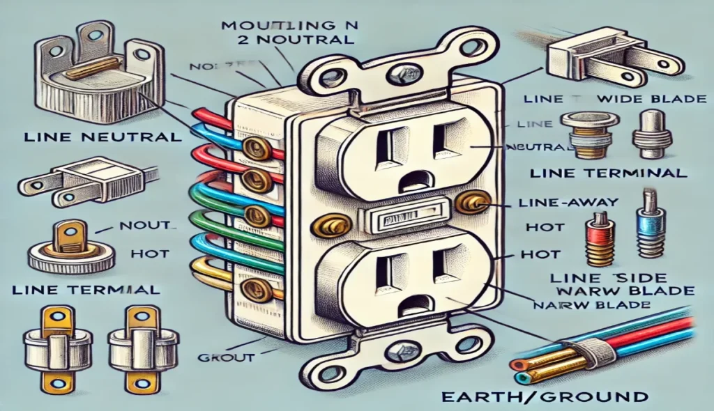
An electrical outlet, also known as a receptacle or socket, is an essential point where you can connect your appliances to draw power. Following the NEC code, these outlets are designed to handle loads efficiently through wiring. Each outlet has screws for connections: brass screws for the hot wire and silver screws for the neutral wire. The ground wire is connected to a green screw, ensuring safe installation. Outlets are vital in every home to run equipment safely and efficiently.
When wiring an outlet, the hot wire from the main breaker should connect to the narrow blade terminal, while the neutral wire connects to the wide blade terminal. The ground wire attaches to the green screw to complete the safety loop. Inside the outlet, brass screws are electrically bonded by a tab, ensuring that connecting one hot wire can feed both terminals. For specific uses, you may need to remove the tab to split the outlet for multiple connections.
From my experience, working with wiring requires precision and safety. Always follow trusted tutorials and check diagrams to ensure the wire connections are correct. When handling breakaway tabs, be cautious as removing them alters the system. Installing outlets in different ways often depends on the desired application and home layout. Whether you’re installing an ordinary or standard outlet, understanding the point of each wire and screw connection is crucial for a safe and effective setup. You can also read VI Characteristics of SCR.
Electrical Outlet Wiring Diagram
Wiring Multiple Outlets in Parallel
When working on wiring, a simple diagram shows that multiple outlets can be connected in parallel to ensure each outlet works independently of the others. Each outlet must be wired using separate cables for reliability. Keep in mind that a series connection is against the NEC code because if one outlet wire cuts or turns faulty, the whole circuit becomes useless. This rule doesn’t apply to GFCI and AFCI receptacles, where series wiring is required for protection. Following these guidelines ensures a safe and effective electrical setup. You can also read De Sauty Bridge.

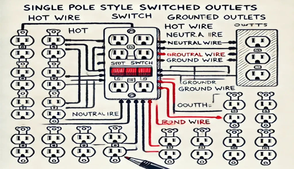
Wiring of Multiple Switched Outlets
In this wiring setup, multiple outlets are wired to a single-pole SPST switch, commonly used in the US for one-way or two-way control. As shown in the figure, the switch is first installed before connecting the hot wire to the parallel-connected outlets. This design allows the switch to feed power to all outlets, ensuring their ON and OFF operation can be easily controlled. Such diagrams are helpful for controlling multiple points with one switch for convenience and efficiency. You can also read Torque Equation of a DC Motor.
Wiring a Switch to an Outlet
In this wiring, a switch is added to an existing outlet by removing the hot wire from the brass terminal. The wire is connected to the first terminal of the switch, and the second terminal is connected back to the brass terminal on the outlet. This setup allows the outlet to be controlled ( ON/OFF ) using the switch for easy power control.

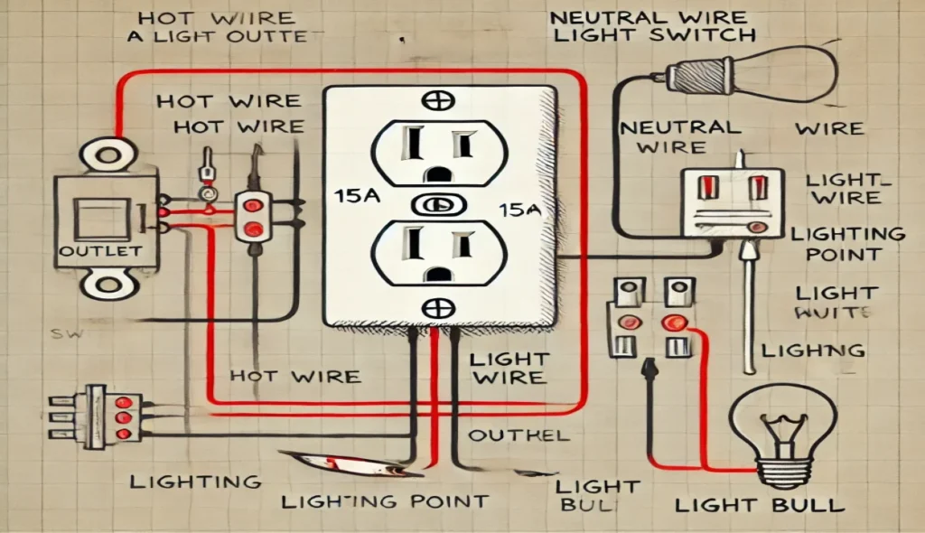
Wiring a 15A Outlet with Light Switch
In this wiring, a switch is added to the existing outlet to control a light. The hot wire from the outlet is connected to the first terminal of the switch, while the second terminal is connected to the lighting point. Lastly, the neutral wire from the outlet is connected to the light bulb for proper circuit flow.
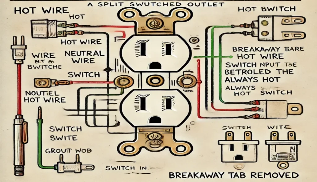
Wiring a Split Switched Outlet
In this wiring, the outlet is split into two parts, where the upper portion is controlled by a switch, and the lower half remains always hot. To achieve this, remove the breakaway tab between the brass terminals as shown in the fig. The switch output (as hot) is connected to the upper terminal, while the lower terminal should be connected to the switch input hot wire.
A common hot wire must be connected to the first terminal of the switch and the lower hot terminal of the outlet. The second terminal of the switch is connected to the upper hot terminal of the outlet. Lastly, ensure the neutral and ground wires are connected properly, as shown in the figure for a safe and effective setup.
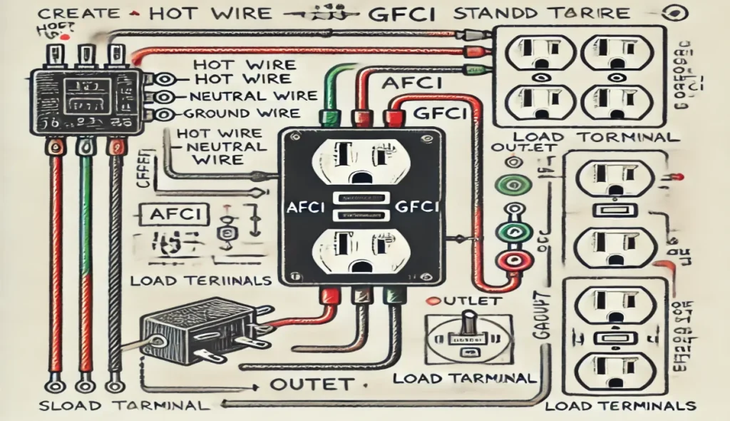
Wiring an AFCI and GFCI to the Outlet
In this wiring, the outlet is connected to the load terminals of the GFCI, while the GFCI is connected to the load terminal of the AFCI. This setup ensures the standard outlet is both AFCI and GFCI protected. For easier installation, you can use a single unit that combines both protection features instead of installing two outlets separately. This series wiring is only acceptable when using AFCI or GFCI for safety.
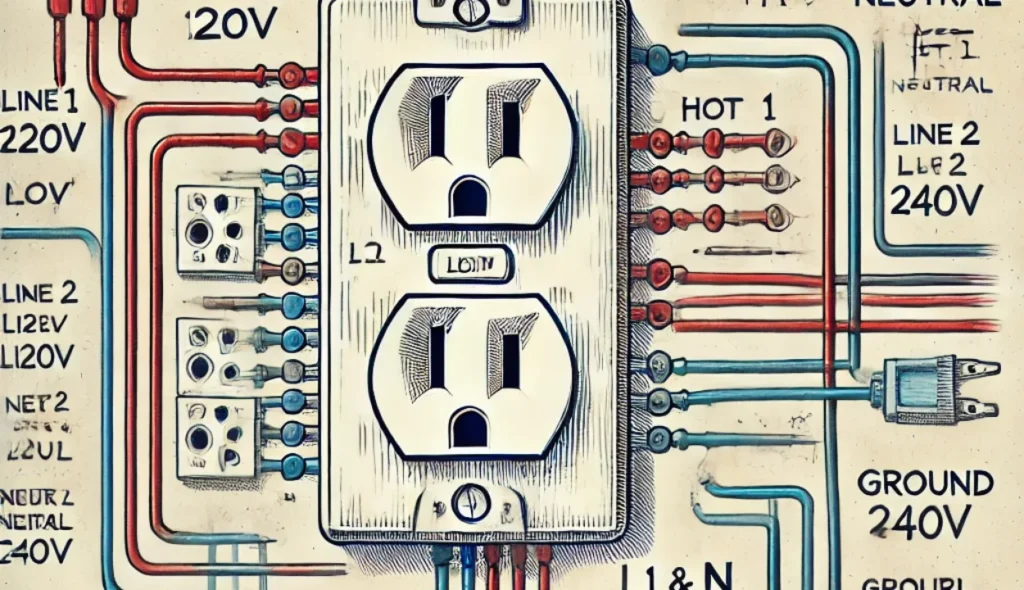
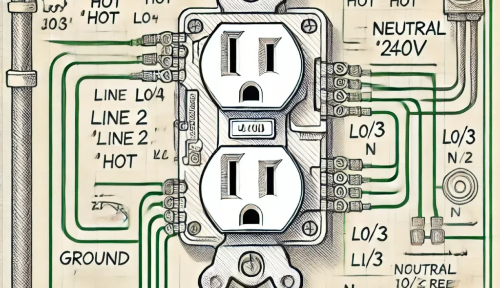
Wiring Dual Outlets from 240V Source for 120V
In this wiring, the first and third outlets are connected to Line 2 (Blue), while the second and last outlets are connected to Line 1 (Red). The neutral wire from the main breaker is connected to all neutral terminals of the outlets. The ground wire is also connected to the outlets, as shown in the figure. This setup ensures the dual outlets from a 240V supply can deliver 120V to the appliances safely.

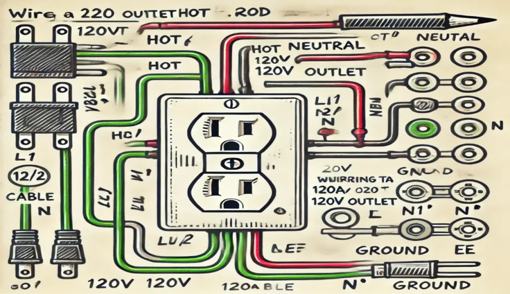
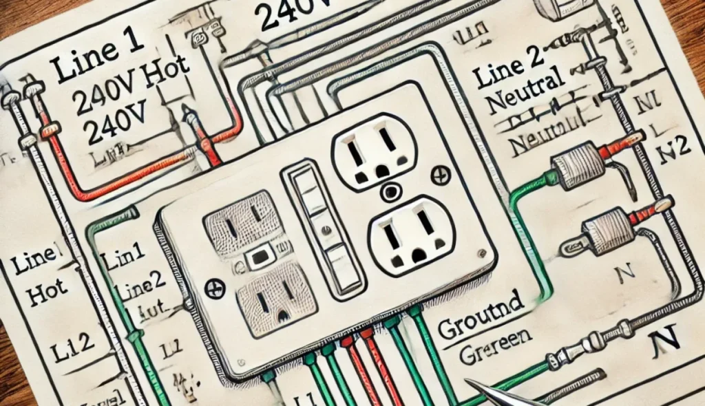
Wiring Combination of 120V and 240V Outlet
In this wiring, a dual outlet can provide both 120V and 240V. The upper portion is connected to Line 1 for 240V, while the lower outlet is connected to Line 2 for 120V. The neutral and ground wires are connected to the brass and ground terminals to ensure proper circuit flow. Special outlets like 5031-I and 5842-I are recommended for this combination.
Keep in mind that no more than 20A should run through a single outlet. For example, a 15A air conditioner on the upper outlet and a 10A heater on the lower outlet will exceed the limit. Alternatively, you can plug low-power devices like 100W bulbs in the 120V outlet while the 240V outlet remains operational without exceeding the total amperage limit.
Wiring 20A, 120V outlet
In this wiring, a 20A 120V outlet is connected to the 120V supply using a hot, neutral, and ground wire for proper power flow and safety.
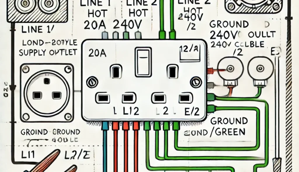
Wiring 20A, 240V outlet
In this wiring, line 1 and line 2 are connected to the brass terminals as required for 240V power. No neutral is needed, and the ground wire must be connected to the ground terminal accordingly for safety.
Wiring 30A, 240V Outlet for Dryer
For this wiring, a 30A, 240V outlet is wired for a dryer using a 10-gauge, 3-wire cable. The Line 1, Line 2, neutral, and ground wires are connected to their related terminals, powered by a separate breaker for safe operation.
Wiring a 50 A, 240 V outlet
For high loads and amperage, use a 6-gauge cable with 3 wires for safe wiring. Connect Line 1, Line 2, Neutral, and Ground to their related terminals as shown in the fig, powered by a separate breaker. Ensure both hot 1 and hot 2 are securely connected for proper voltage flow.
General Information about Electrical Outlets
The brass screws should be connected to the hot wire, which may be black, brown, or red in color.
The silver screws should be connected to the neutral wire, which is usually white or blue.
The green screw is for the ground or earth wire, often green, yellow, or bare.
If the outlet has four prongs, you must connect Line 1, Line 2, the neutral, and ground wires from the breaker.
For 240V outlets, a neutral wire is not required unless the outlet has four prongs.
Follow the correct wiring color codes according to the NEC, IEC, or your local area standards.
Always use a suitable voltage and ampere rating switch with the appropriate wire size and MCB for the load rating.
Precautions
Always switch off the main breaker before starting the wiring to cut the power supply and avoid accidents.
If you are not sure about the wiring diagrams, contact a licensed or authorized electrician for safe installation.
The author is not liable for losses, injuries, or damages caused by the wrong use of this information; electricity is dangerous, so be careful when working with any circuit or outlet.
Conclusion
Wiring an outlet receptacle requires careful attention to safety, wiring diagrams, and correct connections. Always switch OFF the main breaker before starting, and if unsure, contact a licensed electrician for guidance. Following proper wire color codes, using the right wire size, and selecting an appropriate MCB ensures a safe and efficient installation. Remember, electricity is dangerous, and taking precautions can prevent injuries, damage, or losses. Always prioritize safety to ensure a secure electrical setup.