Introduction
Copper losses in transformer is a major factor that affects its overall efficiency, as it occurs when currents flow through the conductors, generating heat and leading to energy dissipation. This loss is unavoidable but can be minimized by optimizing the windings, reducing resistance, and using high-conductivity materials like copper or aluminum.
Unlike no-load loss, which remains constant, copper loss is proportional to the square of the load, meaning it increases as power demand rises. Factors like the proximity effect and skin effect further impact resistance, making calculations more complex in high-frequency applications. Engineers aim to minimize copper loss through advanced winding techniques, improved core design, and efficient power transmission methods, ensuring better performance and energy savings.
What is copper loss in a transformer?
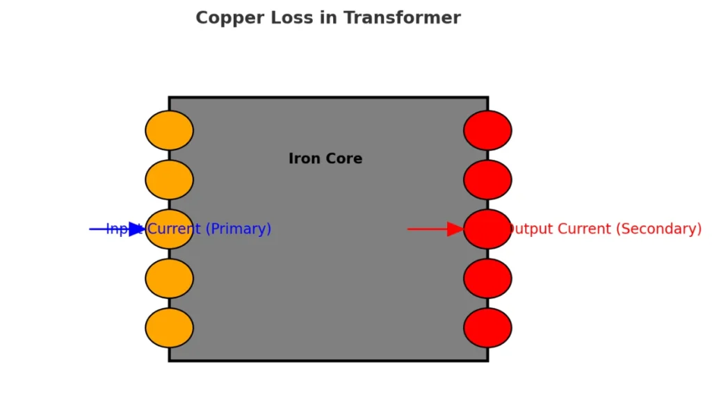
In every transformer, currents flowing through the conductors cause heat, leading to copper loss, an undesirable effect that reduces energy efficiency. Whether copper or aluminum is used, resistance in the winding causes a portion of electricity to be lost as the generator supplies power. This loss is proportional to the square of the load, making it higher with increased demand.
Unlike no-load loss, which occurs even without a consumer, copper loss depends on the transfer of electricity and is affected by induced effects from adjacent parts. Engineers work to reduce these losses by optimizing devices, improving windings, and minimizing resistance in the core, ensuring better delivery and efficiency. You can also read transformer maintenance.
Formula and Calculation of Copper Loss
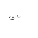
In my experience, copper losses in the transformer are proportional to the square of the current, making it essential to minimize resistance in the windings. According to Joule’s First Law, the energy lost due to heating follows the formula Copper Loss = I² × R × t, where I is the current in amperes, R is the resistance in ohms, and t is the time the current is maintained. The power lost is calculated in watts, and since the coefficient of performance is 1.0, all electrical energy is converted into heat. Therefore, reducing resistance in the conductors improves transformer performance and efficiency
 Where:
I = Current in amperes
R = Resistance of the windings in ohms.
Impact of Frequency on Copper Loss
In low-frequency applications, using conductors with a large cross-sectional area helps reduce power loss by minimizing resistance. However, in high-frequency conditions, the proximity effect and skin effect cause the current to be distributed unevenly, increasing the effective resistance of the conductor. This makes calculations more difficult, but using Litz wire, a special wire constructed to force the current to flow uniformly, helps make the system more effective by reducing Joule heating.
How to reduce copper losses in transformers?
In my experience, reducing power loss in a transformer involves improving the winding technique and using materials with higher conductivity, like copper. Increasing the cross-sectional area of the conductor lowers resistance, helping to reduce losses. In power transmission, voltage is stepped up to decrease current, thereby minimizing energy waste in the stator windings of an industrial motor.
Difference between iron loss and copper losses in transformer
| Aspect | Iron Loss | Copper Loss |
|---|---|---|
| Cause of Loss | Happens due to magnetic effects in the transformer | Happens due to energy dissipation in the copper conductor |
| Type of Loss | Also called no-load loss, does not depend on current | Also called load loss, increases with primary and secondary current |
| Relation with Current | Independent of rated current | Proportional to the square of the current |
| Occurs In | Takes place in the iron core | Happens in the coil due to coil resistance |
| Measurement | Measured at open circuit, does not change with load loss | Measured at short circuit, passing through the coil at 75 ℃ |
| Representation on Nameplate | Not marked on the nameplate separately | Shown as kW rating when the rated current flows through the coil |
Conclusion
Minimizing copper losses in transformer is essential for improving energy efficiency and overall performance. Since this loss is directly proportional to the square of the current, optimizing windings, reducing resistance, and using high-conductivity conductors like copper can significantly reduce energy waste. Additionally, addressing factors like the proximity effect and skin effect in high-frequency applications helps maintain consistent power flow. Engineers continuously refine winding techniques and core materials to enhance power transmission while reducing heat dissipation. By implementing these strategies, transformers can operate more efficiently, ensuring better reliability and longevity in electrical systems.