Introduction
A voltage regulator plays an essential role in designing any electronic system, ensuring a stable and regulated power supply. Whether in a smartphone, wristwatch, computer, or laptop, these devices require a consistent and reliable flow of energy to function properly. Without it, the components inside the circuits may not perform as expected.
There are different types of voltage regulators, mainly AC from mains outlets and DC from batteries. These sources ensure a continuous power supply, preventing fluctuations that could damage electronic devices. This article provides an overview of how these regulators keep systems working efficiently.
What is a voltage regulator?
A voltage regulator is a system that is designed to automatically maintain a constant level of power. It helps to regulate one or more AC and DC voltages, ensuring that electronic devices function properly. Using a feed-forward design or negative feedback, it keeps energy flow stable. Some regulators rely on an electromechanical mechanism, while others use electronic components for precise control.
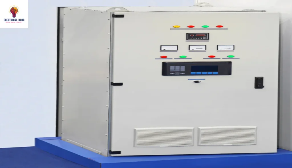
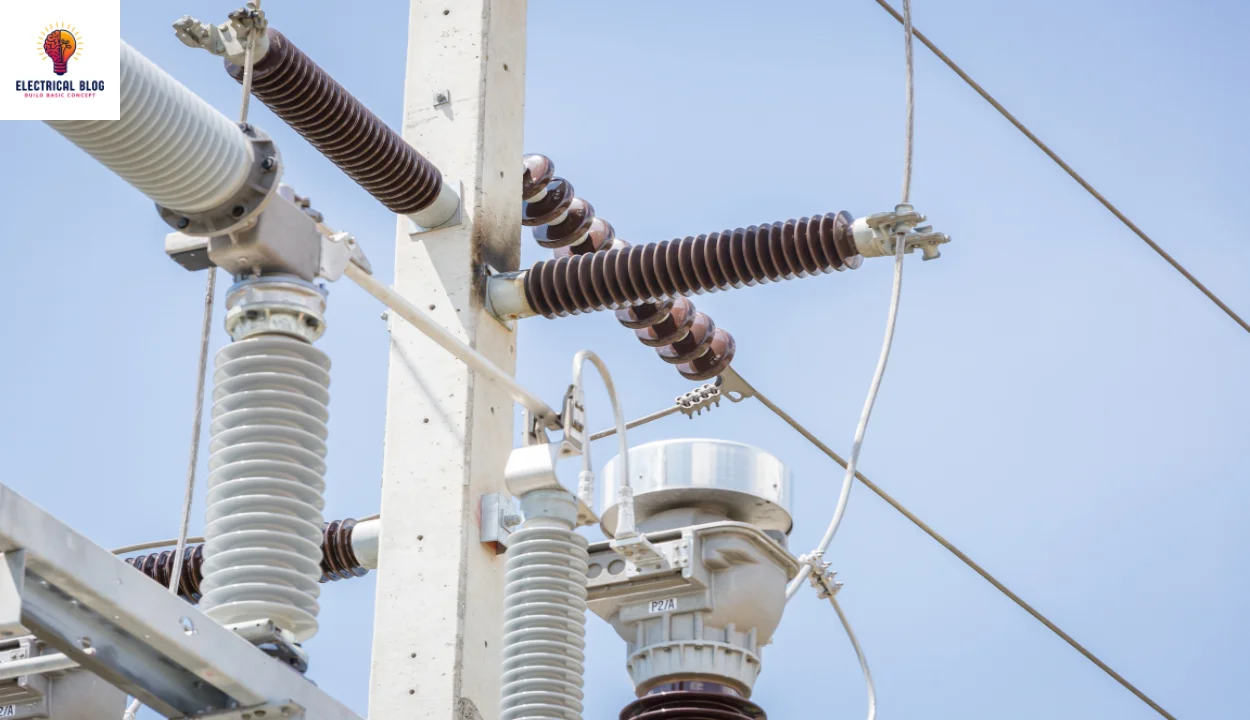
You’ll find voltage regulators in computer power supplies to stabilize the processor and other elements. In an automobile, alternators ensure a steady charge, while central power station generator plants control the output of electricity. In electric distribution, they are installed in a substation or placed along power lines so that customers receive a steady voltage, no matter how much energy is drawn.
How a voltage regulator works
A voltage regulator is a circuit that maintains a fixed output, no matter the changes in input or load conditions. It creates a stable power supply to keep voltages within a safe range. This ensures that all electrical components work properly and remain compatible with the system.
Most VRs are commonly used for DC/DC conversion, but some can perform AC/AC or AC/DC adjustments. They help keep the power stable and prevent disruptions in the supply. Whether in small devices or large systems, they are essential for reliable energy control.
Voltage regulator diagram
Types of Voltage Regulators
Two primary categories of voltage regulators exist: linear and switching. Linear regulators regulate a system’s voltage with low efficiency, wasting excess power as heat. Switching regulators, on the other hand, achieve high efficiency by converting most of the input energy into output without much dissipation.
Linear Voltage Regulators
A linear voltage regulator utilizes an active pass device like a MOSFET or BJT, which is controlled by a high-gain operational amplifier. It works to maintain a constant output by adjusting the resistance after comparing the internal reference with the sampled voltage. This process helps in driving the error to zero, ensuring smooth operation. These are step-down converters, meaning the output remains below the input voltage.
One of the advantages of linear regulators is their easy design, making them dependable and cost-efficient. They produce low noise and ripple, which helps reduce electromagnetic interference. However, they generate heat, so a heatsink is sometimes needed for very large power applications. A popular model like the MP2018 only requires an input and output capacitor to operate, making it an intuitive choice for engineers.
Despite their simplicity and reliability, linear regulators have lower efficiency because they cannot handle fast changes in line and load conditions. They are highly cost-effective but may require more space when increased output is required. Since they regulate by dissipating excess energy as heat, their response time is slower compared to switching regulators. Thus, they are best for low-power applications where less interference is needed.
Switching Regulators
A switching regulator uses a complex circuit design, making it more complicated than a linear regulator. It requires selecting the right external component values and tuning the control loops for stability. A careful layout is important to ensure proper operation and avoid inefficiencies.
These regulators can function as step-down, step-up, or a combination of both, making them highly versatile. One of their biggest advantages is that they are highly efficient, with better thermal performance. They also support higher current and work with a wider VIN/VOUT range.
Some models, like the HF920, achieve greater than 95% efficiency, depending on the application requirements. However, a switching power supply system may need additional parts, such as inductors, capacitors, FETs, and feedback resistors. These features make it a high-reliability solution for precise regulation.
Different Types of Voltage Regulators
Electronic Voltage Regulators
Electromechanical Regulators
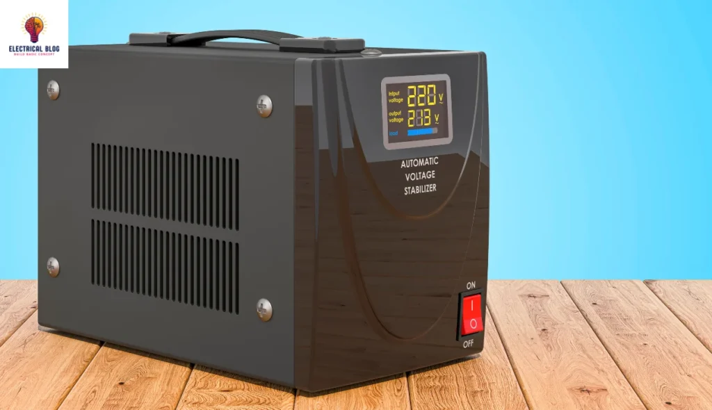
Automatic Voltage Regulator
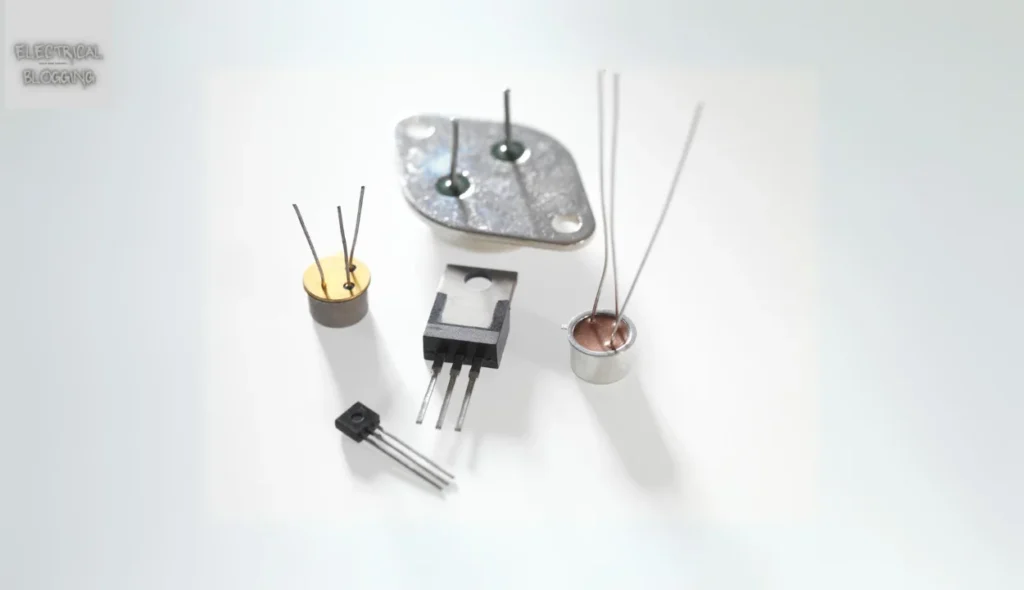
Electronic Voltage Regulators
A simple voltage regulator can use a resistor in series with a diode to provide a stable current. The V-I curves of the diodes help in maintaining control across varying input levels. While this method is efficient for small loads, it lacks precise control and is only useful for low-regulated output. When higher stability is needed, a Zener diode is employed to take advantage of its fixed reverse voltage.
A feedback system operates by comparing the actual output with a reference voltage. Any difference is amplified and used for regulation by adjusting the element that reduces the error. This method forms a negative control loop, improving accuracy but affecting stability. An open-loop design increases gain, but it also introduces risks like oscillation and ringing during sudden changes.
In complex cases, a balance is needed between response speed and stability under increasing load conditions. The regulator is commanded to produce a higher or lower voltage by dropping or drawing more power. A buck regulator reduces voltage, while a boost-type regulator increases it. Some designs include over-current protection to limit damage, and others use crowbar circuits to stop power flow when the input is outside the safe range.
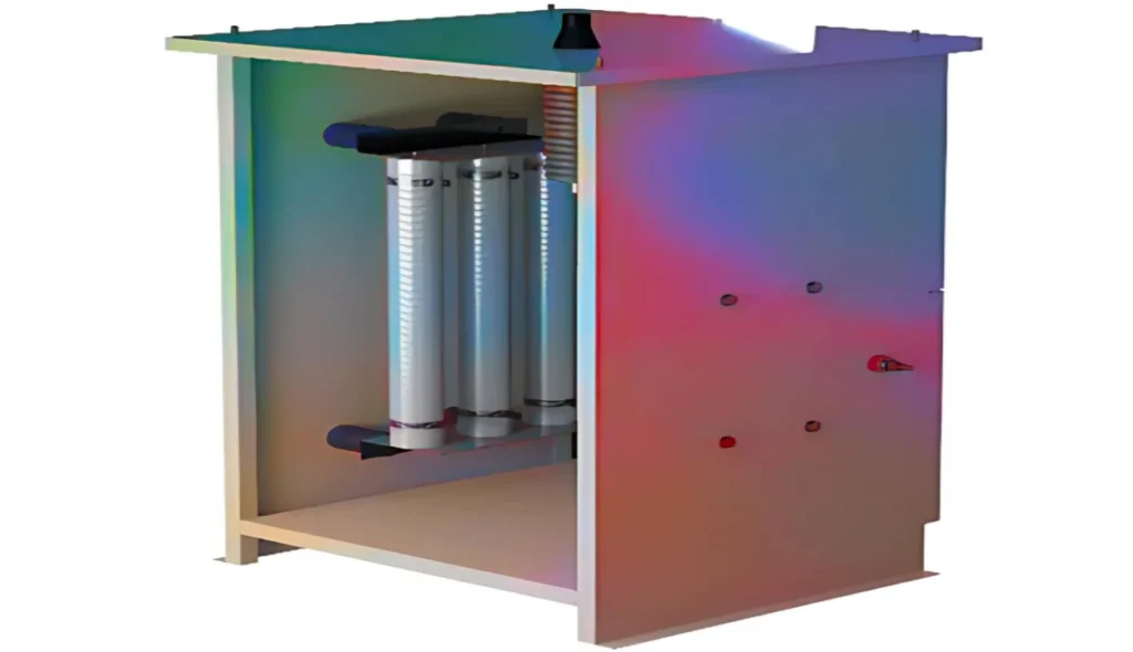
Electromechanical Regulators
Electromechanical regulators help in voltage regulation by using a coiling wire around a sensing electromagnet. The magnetic field produced by the current attracts a moving ferrous core, which is held by spring tension or gravitational pull. As the voltage increases, the coil pulls the core, physically activating a mechanical power switch. When the voltage decreases, the core retracts, releasing the switch to close the circuit and restore flow.
A mechanical design can be sensitive to fluctuations, using a solenoid and a selector to adjust resistances or transformer windings. This allows a gradual step in output changes by rotating the position of a moving-coil AC regulator. Early automobile generators and alternators used one, two, or three relays and resistors to stabilize the generator’s voltage at 6.7V or 13.4V, keeping the battery charged independently of the engine’s rpm.
As the load changes, the pulse in the field adjusts the rotating machine’s strength, ensuring an unloaded voltage per rpm. Unlike capacitors that smooth a pulsed voltage, the inductance stores energy in an iron core, preventing strongly pulsed output. The stator produces an alternating current, while a commutator with graphite brushes on copper segments helps convert AC to DC by switching at the right shaft angle. Modern designs now use solid-state technology with transistors to perform the role of relays, making mains stabilization more efficient.
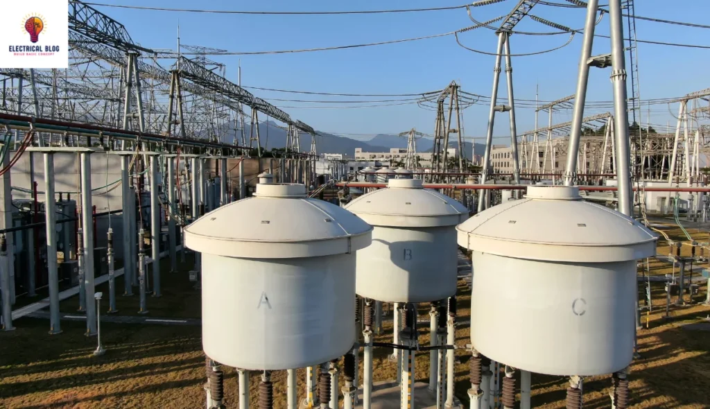
Automatic Voltage Regulator
An automatic voltage regulator (AVR) is used in generators at power stations, ship electrical production, and standby systems. It helps to stabilize voltages as the load changes, ensuring smooth operation. The first AVRs were electromechanical, but modern ones use solid-state devices for better performance.
An AVR works by using a feedback control system that measures the output and compares it to a set point. If there is a difference, it generates an error signal to adjust the excitation current in the field winding. This change increases or decreases the terminal power based on system needs.
In grid-connected systems, multiple generators must be connected in parallel to the transmission grid. The AVR also controls reactive power and ensures all sources operate at the correct factor. Additional features help stabilize the system against upsets, such as sudden loss or faults in the grid.
Voltage Regulator Topologies
Switching regulators use various topologies to control voltage efficiently. The common types include step-down, step-up, and buck-boost converters, each serving different needs. Unlike linear regulators that rely on low-dropout (LDO) designs, these methods adjust power dynamically.
LDO regulators
LDO regulators are a popular topology in linear designs and are designed to operate with a small voltage difference between input and output terminals. Unlike standard regulators that require the input voltage to be at least 2V above the output, low-dropout regulators work efficiently even at 100 mV.
Step-Down and Step-Up Converters
Step-down converters, also known as buck converters, take a larger input voltage and produce a lower output. Step-up converters, or boost converters, conversely work in reverse to produce a higher voltage. These converters are widely used in applications requiring efficient power management.
Buck-Boost
A buck-boost converter is a single-stage design that combines the functions of both buck and boost converters. It helps to regulate the output across a wide range of input voltages, whether greater than or less than the required level. This makes it highly adaptable for varying power needs.
Voltage Regulator Control
A linear regulator uses four fundamental components: a pass transistor, an error amplifier, a voltage reference, and a resistor feedback network. The inputs are set by resistors (R1, R2) to monitor a percentage of the output and compare it to VREF. If the sampled voltage changes, the resistance adjusts to maintain a constant VOUT.
A switching regulator requires more circuit elements, including a power stage that switches between VIN and ground. It works by sending charge packets to deliver the right voltage. An operational amplifier samples the DC output, and the signal is compensated, filtered, and used to modulate the PWM duty cycle, keeping the voltage in regulation.
For example, if the load current increases rapidly, it may cause a voltage droop. The control loop responds by increasing the supply to bring the system back to a stable rail. Using an external capacitor allows the system to operate efficiently, making it easy to implement in different designs.
Linear and Switching Regulator Applications
Linear regulators are ideal for applications that are cost-sensitive, noise-sensitive, or low current. They are commonly used in consumer electronics like headphones, wearables, and Internet of Things (IoT) devices. For example, a hearing aid benefits from a linear regulator since it avoids a switching element that could create unwanted noise and interfere with the device’s performance.
Designers working on a low-cost application can rely on linear regulators when power dissipation is not a concern. However, switching regulators are more beneficial for general use, especially where efficiency is key. They are preferred in industrial, enterprise, and automotive applications where stable power delivery is necessary.
For large step-down voltage requirements, a switching regulator is better suited since it prevents high energy loss. A linear regulator in such cases may cause damage to electrical components due to excessive heat. Therefore, industrial and enterprise sectors often choose switching regulators for better power management.
Limitations of Voltage Regulators
One of the disadvantages of linear regulators is that they are inefficient and dissipate a large amount of power in certain use cases. The voltage drop across them is comparable to a resistor, causing energy loss. For instance, if a 5V input is reduced to a 3V output, the 2V drop limits efficiency to 60%. This makes them best suited for applications with lower VIN/VOUT differentials.
It is important to consider the estimated heat generated in an application, especially with larger input voltages. High energy loss can overheat circuits and damage critical components. Another limitation is that linear regulators are only capable of buck (step-down) conversion, while, in contrast, switching regulators support boost (step-up) and buck-boost conversion, making them more highly efficient.
However, switching regulators also have disadvantages since they are less cost-effective, larger in size, and more complex. If not carefully selected, their external parts can create excessive noise, affecting circuit stability. This is important for a given design, as noise can affect the circuit’s operation and performance, especially in EMI-sensitive applications.
What are the basic parameters for a voltage regulator IC?
When choosing a voltage regulator, there are several basic parameters to consider. The input, output, and current levels help determine if the VR topology is compatible with a user’s IC. These factors ensure stable power management in different applications.
Other key factors include quiescent power use, switching frequency, and thermal resistance. In light-load or standby conditions, efficiency is a priority, and maximizing the frequency leads to smaller system solutions. Feedback also plays a relevant role in ensuring stable voltage regulation.
It is critical to remove excess heat from the device to prevent damage. The controller may have an internal MOSFET, where losses like conductive and dynamic dissipation affect performance. Engineers must examine the lowest voltage the IC can support, ensuring it meets standard reference limits for accuracy and regulation.
How to Pick the Right Voltage Regulator
A designer must understand the key factors when selecting a voltage regulator. The system efficiency, VIN, VOUT, and IOUT should be carefully analyzed to meet the requirements. Other priorities, such as cost, performance, and power control, also play a role in choosing the best option.
Using a parametric search table is a valuable tool that offers different features for a specific application. It helps find a proper device with PG indication, enables functions, and provides additional available options. Once the needs are defined, the table ensures the regulators match the good design specifications.
Conclusion
Voltage regulators are essential for maintaining a stable power supply in electronic systems. They come in different types, including linear and switching regulators, each suited for specific applications based on efficiency, cost, and performance. Understanding the key parameters like VIN, VOUT, IOUT, and thermal management is crucial for selecting the best regulator.
While linear regulators are cost-effective and low-noise, they can be inefficient for high-power applications. Switching regulators, though more complex, provide higher efficiency and flexibility in step-up, step-down, and buck-boost configurations. Designers should use parametric search tools to define requirements and find the proper device that meets system priorities.