Introduction
In my early days with electrical systems, I discovered that engineers often use rheostats to manage current and flow in circuits. Their basic operation leads to many functions. They can adjust resistance levels precisely in both test setups and live environments. Over time, I learned that choosing a rheostat requires key considerations. These include load range and performance characteristics, which must match specific applications. This blog post shares insights from my years of hands-on engineering experience. It highlights how vital these devices are for system control and calibration.
What is a rheostat?
A rheostat is a variable resistor designed to control resistance in a circuit efficiently. Its construction is quite similar to potentiometers, but with a key contrast—it only uses two connections instead of three. The first connection is to one terminal of the resistive element, while the other is linked to the wiper, a sliding contact that moves over the wire-wound core. This design allows smooth adjustments without sudden interruption, making it a significant tool for handling electrical loads. The insulation around the ceramic base prevents overheating, and the wire is carefully wound to ensure stable operation.
Though they were primarily used in power applications, such as heaters, motors, and ovens, they have been replaced in many cases by electronics due to their relatively low efficiency. However, they still exist in specialized roles, particularly in calibration, tuning, and fabrication processes.
For instance, preset resistors and trimpots, sometimes wired as rheostats, are adjusted during circuit setup. This is dedicated to ensuring precise resistance levels. In some cases, they also function as dimmer switches, providing intensity control. Despite modern alternatives, their ability to manage electrical flow remains essential in various applications.
Rheostat Diagram
Symbol of a Rheostat

Working of Rheostat
A rheostat is an essential component in an electrical circuit, designed to control current through changes in resistance. It works by adjusting the position of the sliding contact, which alters the effective length of the resistive material. This change in length directly impacts resistance, as it is dependent on key factors like the type of material and the cross-section of the conductor.
Since current and resistance are inversely proportional, an increase in resistance causes a decrease in current, and vice versa. The voltage applied to the circuit and the parameters determine how smoothly this adjustment occurs.
To ensure accurate control, it has at least three terminals, though only two are used at a time. The fixed terminal serves as one end, while the other connection is made between the sliding terminal and the resistive track. The rating of a rheostat is crucial, as it defines the maximum and minimum resistance offered.
For example, if a given rheostat has a rating of 500 kΩ, its resistance can be adjusted from 0 to 500 kΩ. This flexibility makes them important in circuits that need variable resistance to control flow effectively. Understanding these interdependent aspects helps in selecting the right rheostat for specific applications.
Construction of Rheostat
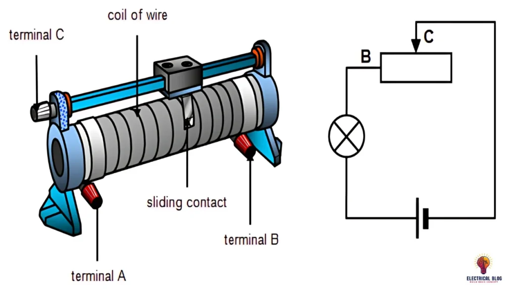
The construction of a switch is similar to a potentiometer, with three terminals labeled A, B, and C. It has two active connections, where either A and B or B and C are connected. The resistive element is placed along a track, and a wiper moves over it to adjust the resistance. The slider is attached to the wiper, allowing it to modify the path of the current. The resistance depends on the length of the loop of wire, and the positioning of the wiper influences how its switch operates. This structure is shown in the figure below, highlighting how the fixed parts remain stable while the uneven parts adjust to change the resistance.
Types of Rheostats
Linear Rheostat
A linear rheostat is a variable resistor with two terminals, where a wiper moves along a wire coil, adjusting resistance and current flow. It is called a slide rheostat because its operation takes the form of a sliding slider. Moving the contact in one direction lengthens the path of electricity’s journey, increasing resistance and decreasing current. In the opposite direction, the path shortens, reducing resistance and forcing more current across the circuit. These are often used in testing and laboratory environments, especially for checking stability in mechanical and electrical systems. Their position on an insulating surface helps ensure safe operation.
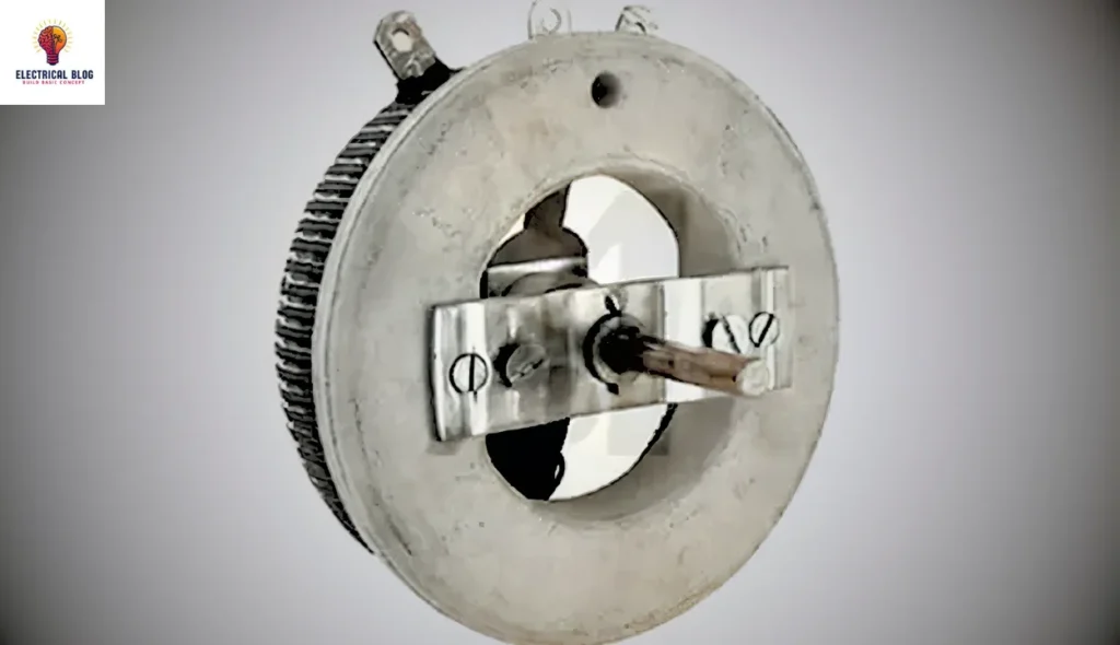
Rotary Rheostat
A rotary rheostat is a type of resistive device that controls current by adjusting the wire coil arranged in a horseshoe or U-shape. Unlike a linear version, it is controlled using a dial or knob, which pulls the wiper back and forth around the coil.
When the wiper moves, the length of the resistive path extends or shortens, which directly affects the resistance and current. A longer path increases resistance, leading to a lower current, while a shorter path decreases resistance and provides a higher current. This inverse relationship is the same as in other types, but the operating mechanism in a rotary model allows for smoother adjustments. The fixed and sliding terminals ensure stable contact as the wiper moves around, making it reliable for various applications.
Preset Rheostat
A preset rheostat is a small component commonly used in calibration circuits where precise resistance control is needed. These types of are known as trimmers and are designed for fine adjustments in a circuit. They are usually found on a printed board and are adjusted during setup or maintenance. Engineers commonly rely on these types in delicate electronic applications, where either manual tuning or automatic adjustments are required.
Rheostat vs Potentiometer
| Feature | Rheostat | Potentiometer |
|---|---|---|
| Function | Used to control the amount of current flowing in a circuit. | Used to divide voltage between two points in a circuit. |
| Terminals | Has two terminals – one end and a sliding contact (wiper). | Has three terminals – two ends and a center wiper. |
| Connection in Circuit | Connected in series with the load, so it controls the current directly. | Connected in parallel, typically between voltage source and load. |
| Application | Common in high-power devices like heaters or motors. | Used in low-power electronics for fine voltage adjustments. |
| PCB Connections | Requires fewer connections, making it simpler to mount. | Needs more connections due to three terminals. |
| Taper Type | Offers a linear taper, meaning resistance changes evenly. | Can offer linear or logarithmic taper depending on the need. |
| Adjustment Type | Changes resistance to control how much current flows. | Changes voltage output by adjusting the wiper’s position. |
| Design | More robust and simpler for heavy-duty use. | More versatile for sensitive, precise control applications. |
| Wiper Role | Wiper slides along a wire coil to increase or decrease resistance. | Wiper selects voltage level between input and ground. |
| Practical Use | Best when only current control is needed. | Best when a specific voltage output is required. |
| Resistance Change | Resistance changes smoothly and steadily as the wiper moves. | Resistance may change smoothly or logarithmically, useful in audio controls. |
Practical Uses of a Rheostat
In lighting systems, they are perfect for dimming control, adjusting light intensity to suit room needs or save energy.
They are ideal devices for power management in motor speed regulation and heating equipment like heaters, offering reliable and adjustable performance.
As a variable resistive load, it can simulate different loads during the study of new circuit designs, making complex setups easier to study and test.
I’ve often used them in testing environments where switching electronics were either not available or needed to be replaced with something simpler and more stable.
These devices are also common in classrooms, where students can easily find and observe how voltage and current react to changes, making concepts easy to understand.
Whether it’s a single device or part of a broader system, the rheostat finds a reliable role across various applications in both learning and practical fields.
Conclusion
Rheostats may look simple, but they are key for controlling current and adjusting resistance. They are valuable in schools and industries. Whether fine-tuning equipment, simulating loads, or dimming lights, they offer reliable benefits. This is true even with the rise of digital options. Knowing the types, construction, and uses of rheostats helps engineers and learners make better choices in designing or fixing electrical circuits. From my experience, mastering them is a small step that leads to big gains in precision and control.
FAQs
Why is a rheostat used in Ohm’s law?
A rheostat is used in Ohm’s law experiments to vary the resistance in a circuit, which helps demonstrate the relationship between voltage, current, and resistance. By adjusting the rheostat, students and engineers can see how changing resistance affects current flow, making it easier to understand the law in action.
Is a rheostat a dimmer switch?
Yes, in some lighting systems, a rheostat functions like a dimmer switch by reducing the current flowing to a light, which in turn dims its intensity. However, modern dimmers often use electronic circuits instead for greater efficiency.
Is a rheostat a resistor?
A rheostat is a kind of adjustable resistor. Unlike fixed resistors, it allows for adjustable resistance, which is useful for controlling current in real-time without turning off the circuit.
How to test a rheostat?
To test a rheostat, use a multimeter set to measure resistance (ohms). Connect the multimeter to the terminals and move the wiper. A gradual variation in resistance should be observed. It is expected that there will be a gradual shift in resistance. If the resistance jumps or remains the same, the rheostat may be malfunctioning.