Introduction
While working on high-frequency circuits, I once came across a simple yet incredibly versatile component—the Step Recovery Diode (SRD). Though not as common as other types of diodes, the SRD stood out due to its unique characteristics and niche applications. Often called a snap-off or charge-storage diode, it stores energy in a way that allows rapid recovery, making it useful in sharp pulse generation. This article shares key information from that experience, highlighting why understanding this type of diode is a technical requirement for those dealing with varactor-based devices in microwave systems.
What is a step-recovery diode?
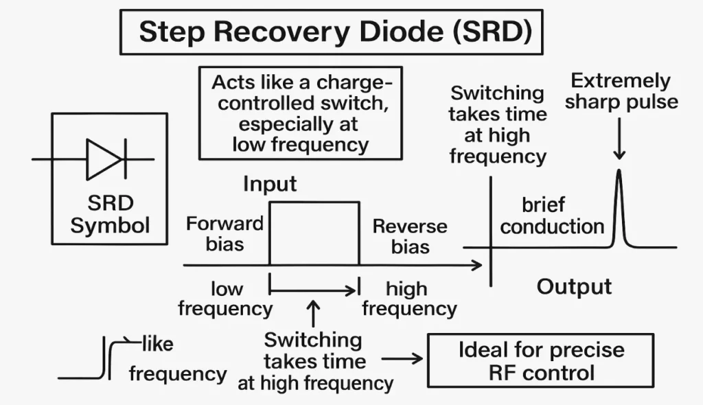
In my RF circuit design projects, I’ve used the step recovery diode (SRD) to generate extremely sharp pulses with great speed. This special semiconductor acts like a charge-controlled switch, especially at low frequencies, and its symbol is often shown in high-speed switching guides. It operates differently from a normal diode, and that’s what makes it stand out.
The working process is quite similar to any forward or reverse-biased circuit, but the SRD instantly changes its condition when switching from forward to reverse. At high frequencies, this switching takes time, and though it’s open in reverse, it can still conduct briefly. This makes it ideal for precise RF control even at less predictable frequencies. You can also read Varactor Diode.
Step Recovery Diode Symbol and Diagram
Step Recovery Diode Construction
In my lab experience, building the structure of an SRD feels similar to a normal diode, but with unique doping near the junction. The intensity of doping is much less, especially around the PN interface, which influences how charge carriers behave. Its design, inspired by the Shockley model, uses two series PN junctions and an extra terminal for input voltage. This layout exhibits special dynamic switching characteristics not found in a single diode.
Because of fewer carriers and charge near the junction, the switching time is in nanoseconds, ideal for high-speed circuits. When switching from forward to reverse bias, only a small amount of charge needs to move, which makes it fast. This speed is visible in its doping profile, often shown in technical diagram references. The recovery is clean and fast, even with low frequencies in the system.
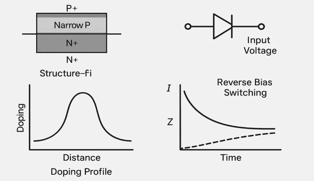
During the negative input cycle, I noticed some residual current due to the slow drain of stored charge. Initially, this impedance is close to 1 ohm; then it starts increasing as storage builds up at the junction. This behavior is typical for SRDs at lower frequencies but critical for pulse shaping. Overall, this precise construction allows the step recovery diode to deliver sharp transitions and high performance. You can also read Vacuum Diode.
Step Recovery Diode: Working and Characteristics
I’ve worked with step recovery diodes in several pulsed RF circuits, especially where fast switching and high peak voltage are needed. These diodes are designed for repetitive operations and offer unique characteristics during switching. Their ability to handle high current with minimal shortfall makes them ideal for sharp pulse generation.
The working of this diode depends on how charges build up in the junction region and then release during reverse bias. At a certain critical point, it undergoes avalanche breakdown, allowing electrons to flow freely. This sudden conduction causes intense heat generation, which must be managed carefully.
In forward bias, it behaves like a normal diode, storing minority carriers in the p-n region. These carriers are then quickly depleted during reverse transition, ensuring a clean recovery. The charged capacitance between junctions helps in storing energy temporarily.
Once the stored charge disappears, the reverse current instantly drops to zero, eliminating tailing effects. This sharp recovery feature is what separates it from other diodes. I often see its use in systems requiring consistent conduction over time.
Another interesting characteristic is its negative resistance, which allows more current to flow as voltage decreases. This rare phenomenon helps in building oscillators and amplifiers using these diodes. It’s quite fascinating to see energy being extracted from what seems like a drop in voltage.
At low frequency, the diode performs just like a regular forward-biased diode. But as doping decreases, the response becomes faster and more suited for advanced operation. This entire working model is about managing capacitance, carrier flow, and timing precisely.
Step Recovery Diode Circuit
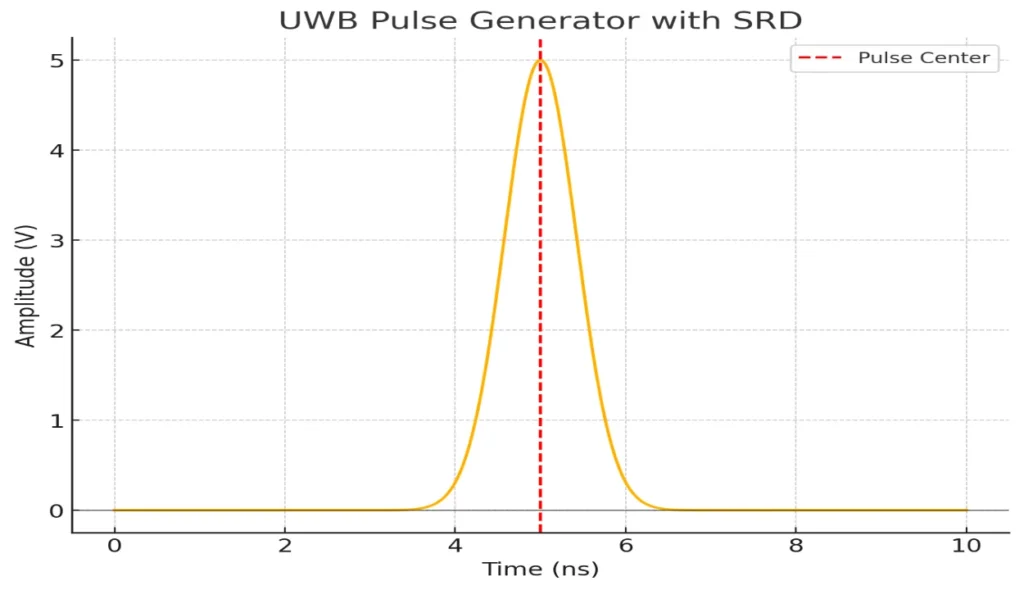
I recently worked on a UWB pulse generator circuit using an SRD and found its implementation both efficient and exciting. The principle is to use the quick recovery characteristics of the step diode to form a sharp pulse with a fast rise time. A resistor R and load RL help shape the input and output signals for better performance. This setup supports wireless and carrierless communications in ultra-wideband technology.
The final measured pulse width was around 600 ps at a 5V amplitude, which worked great in practical applications. Even though there was some buzzing and slightly low amplitude, it was still useful for sub-nanosecond transmission. The circuit performed well in radar systems requiring narrow nanosecond pulses at a medium level. The waveforms were clearly shown in the test diagram we built.
Different IC packages
DO (Diode Outline) and TO (Transistor Outline) are some of the traditional outline types used in step-recovery diodes.
SOD (Small Outline Diode) and SOT (Small Outline Transistor) are compact packages for surface-mounted assembly.
The MELF (Metal Electrode Leadless Face) style includes MicroMELF, MiniMELF, and QuadroMELF for precision diode packaging.
DPAK and D2PAK are discrete power packages often used when moderate heat dissipation is needed.
SC-74, SC-76, and SC-59 are plastic-based, surface-mounted types, typically with three leads for circuit integration.
Powermite®3 offers a compact, high-power solution with excellent thermal performance for rectifier use.
These packages provide different levels of density, depending on the mount type and resistance needs.
I’ve personally used MiniMELF and DPAK styles when space and low thermal resistance were design constraints.
Face contact and electrode design in metal housing ensure solid performance in high-speed switching.
For step-recovery diodes, package choice matters based on heat handling, frequency, and board layout efficiency.
Advantages of Step Recovery Diodes
Step recovery diodes are inexpensive compared to other high-speed diodes, making them cost-effective for many applications.
They have a quick response time, allowing them to operate efficiently in circuits that require fast switching.
Switching time is low, meaning they can handle high-frequency signals without delay.
The diode can generate very sharp pulses, which are ideal for pulse generators and high-precision applications.
The capacity of these diodes to handle highly efficient current flow reduces power consumption.
Their simple design makes them easy to integrate into different systems without complex modifications.
They also have low power loss and reverse recovery time, making them reliable and effective for long-term use.
Disadvantages of Step Recovery Diodes
One main drawback of the step recovery diode is that its switching speed decreases as the frequency increases.
It is not applicable for higher frequencies, limiting its use in some high-speed applications.
If the input-output difference is too high, the efficiency of the diode becomes low, making it less efficient.
Heat dissipation becomes a concern, and the diode may need a heatsink to prevent overheating.
This diode is capable of exclusively step-down operations, which means it can’t handle step-up or other complex tasks.
Applications of Step Recovery Diodes
SRDs are used in high-speed pulse shaping and frequency multipliers.
These diodes can multiply the signal frequency by up to 20 times, making them efficient for many applications.
They are an outstanding component for microwave frequency doubling.
SRDs are also useful in harmonic generators and oscillators, especially in VCOs (voltage-controlled oscillators).
The diode is often used as a parametric amplifier or pulse generator in microwave electronics.
SRDs are key components in frequency synthesizers, comb generators, and sampling phase detectors.
In microwave applications, SRDs offer high efficiency and precision.
The diode is used to generate harmonic signals in various RF systems.
Conclusion
The Step Recovery Diode (SRD) is key in high-frequency circuits. It is used in pulse shaping, frequency multiplication, and harmonic generation. Its unique switching characteristics and ability to generate sharp pulses make it invaluable for microwave electronics and high-speed operations. Step Recovery Diodes are key parts in devices such as VCOs, amplifiers, and pulse generators. They play important roles in radar systems, frequency synthesizers, and phase detectors.
The Step Recovery Diode has benefits like low power loss and fast recovery. However, it struggles with lower switching speeds at high frequencies and can only handle step-down operations. Additionally, heat dissipation can become an issue, requiring solutions like heat sinks. The SRD is versatile for pulse generation and frequency multiplication at lower frequencies. This makes it a dependable part for precise RF systems. Choosing the right IC package and design factors is key for better performance. This includes things like dopant intensity and junction capacitance.