Introduction to Single-Phase Semi Converter
Power converters are vital in power electronics. They change electrical energy from one form to another. They are classified into various types based on their operation, including AC to DC converters and DC/DC power converters. Each type of converter regulates its output to meet application needs. It uses devices like SCRs (Silicon Controlled Rectifiers) and diodes.
A single-phase semi-converter is a type of controlled rectifier. It partially regulates the output DC voltage using two SCRs and two diodes. This converter provides adjustable DC output. It controls the SCR firing angle. This sets the voltage and current characteristics. The single-phase semi-converter is common in small motor drives. They need limited control over power flow.
The main difference between a semi-converter, a full converter, and an uncontrolled converter is the control each provides. A full converter uses four SCRs to allow full control of the DC output, providing greater flexibility and efficiency. An uncontrolled converter uses only diodes. It has no control over the output. However, it is a simple and cheap way to convert AC to DC.
Circuit Diagram and Key Components
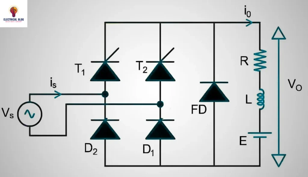
The single-phase semi converter circuit comprises:
- Two SCRs (T1 and T2): Responsible for controlling the conduction phase.
- Two Diodes (D1 and D2): Work with the SCRs to form a bridge for current flow.
- Freewheeling Diode (FD): Positioned parallel to the load to dissipate stored energy in the inductor during intervals when neither SCR is conducting.
- Load (RL or RLE): Typically an inductive load such as a motor or a resistive-inductive load, with or without an emf component.
Basic Components and Circuit Structure
A single-phase semi-converter circuit has three parts: thyristors (SCRs), diodes, and a load resistor. Each of these components of single-phase semi-converter plays a specific role in controlling the output and the behavior of the circuit.
Thyristors (SCRs): The Silicon-Controlled Rectifiers (SCRs) act as controllable switches. When triggered at a specific angle through the gate, these devices allow current to flow in a controlled manner. This lets the converter adjust the output voltage and current. This controllability is fundamental in applications where output regulation is necessary.
Diodes: The diodes in the circuit ensure that current flows in the correct direction. They act as rectifiers. They work alongside SCRs to create a controlled output by only allowing current to pass through when the SCRs are triggered.
Load Resistor: The load resistor represents the device or system that receives the output from the converter. This resistor is in the circuit to dissipate power. Its value affects the current flow.
Operating Principle of Single-Phase Semi-Converter
A single-phase semi-converter is a rectifier circuit. It uses thyristors and diodes to convert AC voltage into a controlled DC output. This controlled rectification gives partial control over the output voltage and current. It does this by adjusting the thyristor’s firing angle.
Controlled Rectification Using Thyristors
In a single-phase semi-converter, thyristors (SCRs) control when conduction starts in the AC waveform. Adjusting the firing angle sets when the thyristor turns on. This allows current to flow through the circuit and affects the DC output voltage. By using both thyristors and diodes, the semi-converter can regulate power to the load resistor.
Firing angle concept and its effect on output
The firing angle is the angle at which the thyristor is triggered within each AC cycle. A smaller firing angle results in a higher DC output voltage since conduction starts earlier in the cycle. Conversely, a larger firing angle reduces the DC output, as conduction begins later. This adjustment enables precise control over the voltage supplied to the load.
Different modes of operation are based on the firing angle and load conditions
A single-phase semi-converter’s mode varies with the firing angle and load.
Continuous Conduction Mode: It occurs with an inductive load. It maintains current flow throughout the entire AC cycle.
Discontinuous Conduction Mode: It occurs in resistive loads or with large firing angles. Here, current flow stops periodically within each cycle.
Working Principle of the Single-Phase Semi-Converter
The operation of a single-phase semi-converter is divided into two main periods based on the AC input’s half-cycle:
Positive Half-Cycle (0 to π radians): During this interval, SCR T1 and diode D1 conduct, delivering current to the load.
Negative Half-Cycle (π to 2π radians): Here, SCR T2 and diode D2 conduct, reversing the current direction and providing controlled rectification.
The firing angle (α) determines when the SCRs turn on within each cycle, which in turn controls the portion of the AC waveform contributing to the DC output.
Positive Half-Cycle (0 to π)
The AC source voltage is positive, forward-biasing SCR T1 and diode D1.
When the gate pulse triggers SCR T1 at angle α, SCR T1 and diode D1 conduct, allowing current to flow through the load.
The output voltage during this phase is approximately equal to the source voltage (Vs) from angle α until π.
SCR T1 turns off when the AC source crosses zero, entering the negative half-cycle.
Negative Half-Cycle (π to 2π)
The AC source voltage reverses, forward-biasing SCR T2 and diode D2.
SCR T2 triggers at π + α, conducting with D2 and supplying current through the load in the opposite direction.
The output voltage is once again a function of the AC source, but in reverse polarity.
The freewheeling diode conducts when both SCRs are off, protecting the circuit from overvoltage and dissipating inductor energy.
Waveforms and Operating Phases
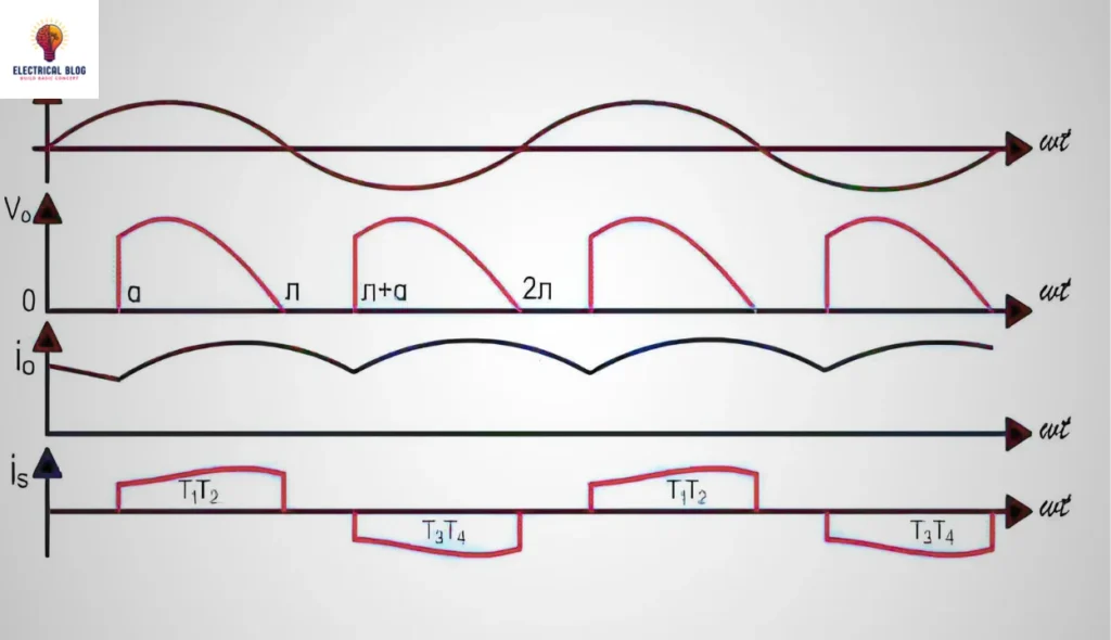
The waveform of the output voltage is crucial for analyzing the behavior of the single-phase semi-converter. The output voltage appears in intervals based on the firing angle and exhibits the following characteristics:
Positive Conduction Period (α to π): When SCR T1 conducts, the output waveform follows the positive half of the AC source.
Negative Conduction Period (π + α to 2π): SCR T2 conducts, creating a negative half-cycle in the output.
The load current’s waveform can be influenced by the freewheeling diode, which smooths current variations and limits the effect of inductance in the load.
Output Voltage Calculations
To calculate the average DC output voltage (Vdc) and RMS output voltage (Vrms), the following formulas are used:
Average Output Voltage (Vdc):
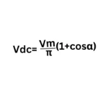
where:
Vm is the peak AC voltage.
α is the firing angle.
RMS Output Voltage (Vrms):
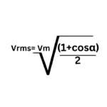
By adjusting the firing angle α, the output voltage can be precisely controlled, which is a critical feature in many industrial applications.
Turn-Off Time and Freewheeling Action
Turn-Off Time of SCRs
The turn-off time (t_q) of SCRs is the minimum time required for the SCR to recover its blocking capability after conduction. Proper synchronization of the firing pulses is essential to prevent overlap and ensure that each SCR has adequate time to turn off.
Role of the Freewheeling Diode
The freewheeling diode (FD) plays a key role in stabilizing the output by:
Preventing overvoltage when both SCRs are off.
Circulating current within the load during non-conductive phases reduces stress on the components.
Applications of Single-Phase Semi-conductors
Single-phase semi-converters are popular for small-scale power control. They are efficient and cheap. They provide a controlled DC output. Here are some common applications:
DC Motor Drives: Single-phase semi-converters are often used for DC motor speed control. They reliably manage motor speeds in applications needing precise control.
Heating Controls: In resistive heating, single-phase semi-converters allow efficient power control. So, they suit small domestic and industrial heating controls.
Battery chargers: These converters are also used in battery chargers. They are important where adjustable DC voltage is needed to optimize charging times and maintain battery health.
Advantages and Limitations
Advantages: Single-phase semi-converters are efficient and cheap. They’re also simple to implement. So, they are ideal for small-scale power control.
Limitations: They produce a high ripple in the output. Their use for inductive loads is limited, as performance decreases with them.
Comparison with Other Converters
Semi-converters and full converters differ in efficiency, power quality, and control.
Efficiency: Full converters, which use four SCRs, are more efficient than semi-converters, which have two SCRs and two diodes. The full converter can better manage the conduction angle, enhancing overall efficiency in converting AC to DC.
Power Quality: Full converters produce a smoother DC output with fewer ripples. Their controlled firing capabilities make this possible. Conversely, semi-converters have higher ripple voltage. Their mix of controlled and uncontrolled components can affect connected devices’ performance.
Control: The control capabilities differ significantly. Full converters allow more flexibility in controlling output voltage and current through phase control. Semi converters provide limited control since the diodes operate without external triggering. This leads to less adaptability.
Brief Comparison with Other Rectifier Types
Controlled rectifiers (like full converters) offer better output control than uncontrolled ones (like diode bridges). The latter can’t adjust voltage or current and rely on the input AC waveform.
Practical Example and Simulation
Step-by-Step Walkthrough of Simulating a Single-Phase Semi-Converter in MATLAB
Simulating a single-phase semi-converter in MATLAB involves the following steps:
Set up the MATLAB environment:
Open MATLAB and create a new script or Simulink model.
Ensure you have the required toolboxes installed, specifically Simulink and Power Systems.
Build the Circuit Model:
Drag and drop the required components from the Simulink library, including SCRs, diodes, and the AC voltage source.
For a semi-converter, you will need two SCRs and two diodes connected in a bridge configuration.
Configure Component Parameters:
Set the input parameters such as the firing angle (e.g., 30°, 60°) and the frequency (50 Hz) of the AC supply.
Specify load parameters, such as an inductor or resistive load, to observe the output waveforms effectively.
Implement Control Logic:
Use a PWM generator to control the firing angle of the SCRs. You can do this by using the Firing Angle Control block from the Simulink library.
Run the simulation:
Click on the Run button to start the simulation. Observe the waveforms produced at the output terminal.
Utilize scopes to visualize the output voltage and load current over time.
Visualizations of waveform results
After the simulation, you can analyze the output waveforms for different load configurations and firing angles.
For low firing angles (e.g., 30°), you will notice a higher output voltage with reduced ripple.
Increasing the firing angle (e.g., to 60°) will show a decrease in the average output voltage and an increased ripple voltage in the waveform.
You can learn how the single-phase semi-converter works. Adjusting these parameters will show you the effects of different control methods on its performance.
Conclusion
A single-phase semi-converter is key in power electronics. It enables controlled rectification of AC to DC. Its efficiency is notable with resistive (R) and resistive-inductive (RL) loads. It shows how the firing angle can greatly affect the output voltage and current waveforms. Semi-converters are very versatile. They are used in many applications, like motor speed control and power supply systems. These require precise power control.
For those interested in a deeper understanding, I suggest practical experiments with MATLAB simulations. They can provide valuable insights into their behavior under different conditions. Further reading on power electronics and lab work can help. It can improve understanding of their design and real-world uses.

