Introduction
When we begin exploring DC voltage, it’s important to pay attention to how it differs from AC voltage. Unlike alternating current, DC maintains a steady voltage level between two points, creating a constant potential difference. In electrical and electronic circuits, this steady flow is crucial for many applications, from batteries to power supplies.
To define DC voltage, we must look at its measurement and symbolic representation as per industry standards. The name itself signifies direct flow, and different methods exist to measure it accurately. Various wire color codes are used in different types of systems based on global standards. Let’s discuss these details further in this article to ensure a solid understanding of this essential term.
Understanding DC Voltage
DC voltage is a type of voltage where the current flows in only one direction without any change over time. It can be either constant or variable, depending on whether its magnitude remains steady or varies. Unlike alternating current, DC voltage has zero frequency, meaning its polarity never reverses.
This type of voltage is commonly obtained from a battery, cell, or DC generator. Since its polarity remains unchanged, it is essential for electronic circuits that need stable power. The abbreviation “DC” stands for “Direct Current,” highlighting its key property of maintaining a steady flow of energy.
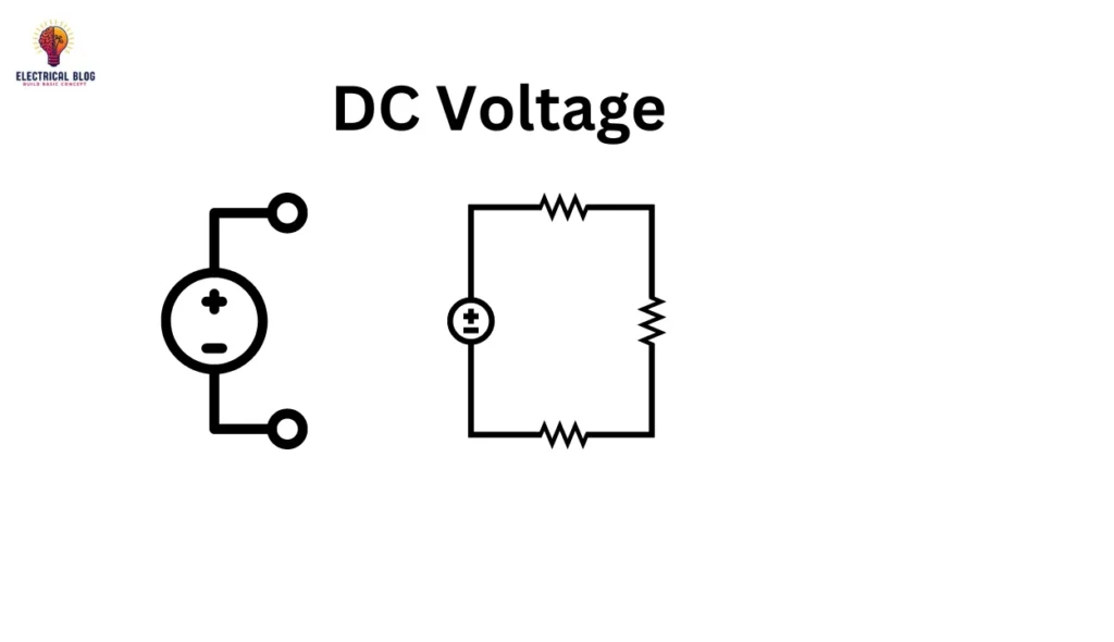
DC Voltage symbol

Standard Wire Colors for DC Voltage
In electrical wiring, different colors of wires help identify the polarity of a wire in DC wiring. This color coding is mainly used to ensure safety and simplify maintenance tasks. There are two major color coding schemes: the IEC DC Power Circuit Wire Color Codes and the US DC Power Circuit Wire Color Codes, which professionals use in various systems.
IEC DC Power Circuit Wire Color Codes
The International Electrotechnical Commission (IEC) sets a standard for color codes in DC systems to ensure safe wiring. Different circuits have unique colors assigned to identify their function. Below is a comparison of wire names and labels with their respective wire colors based on the IEC guidelines.
| DC System | Wire Name & Label | Wire Color |
|---|---|---|
| Ground (Earth) | PE | Green-Yellow Strips |
| Two wire ungrounded DC circuit | Positive (L+) / Negative (L-) | Brown / Grey |
| Two wire grounded DC circuit | Positive (L+) / Negative (M) | Brown / Blue |
| Three wire grounded DC circuit | Positive (L+) / Mid-Wire (M) / Negative (L-) | Brown / Blue / Grey |

US DC Power Circuit Wire Color Codes
The National Electrical Code (NEC) provides recommendations for DC voltage wiring but does not define colors for ungrounded DC systems because they are considered unsafe. The Wire Name & Label for different DC system configurations and their respective Wire Color are listed below.
| DC System | Wire Name & Label | Wire Color |
|---|---|---|
| Protective Ground (Earth) | PG | Bare conductor, Green, Green-Yellow Strips |
| Two wire ungrounded DC system | Positive (L+) / Negative (L-) | No recommendation (Red / Black used) |
| Two wire grounded DC system | Positive (L+) / Negative (N) | Red / White |
| Three wire grounded DC system | Positive (L+) / Mid-wire (N) / Negative (L-) | Red / White / Black |
Methods of Reducing DC Voltage
Sometimes, it is required to reduce the DC voltage before it is applied to a load to prevent damage. For example, a battery of 9 V powering an LED rated at 3 V needs adjustment. In this case, resistors and diodes are commonly used to safely regulate the voltage.
Reduction of DC voltage using resistors
To reduce the DC voltage, we can use a voltage divider circuit made from resistors connected in series. The total input voltage (V) is split into multiple voltages across R1 and R2. By using the equations:
VR1 = (R1 / (R1 + R2)) V
VR2 = (R2 / (R1 + R2)) V
We can calculate the values of R1 and R2 to obtain the desired voltage.
Reduction of DC voltage using diodes
One way to reduce the DC voltage is by using diodes in series. A 9 V battery can be connected with multiple diodes to drop the voltage. For example, if each diode has a 0.7 V voltage drop, it can reduce the voltage from 9 V to 5.5 V, leaving the remaining 3.5 V across the diodes. The germanium diode has a smaller drop of about 0.3 V, while a silicon diode has a drop of around 0.6 V.
How to Increase DC Voltage?
To increase DC voltage, you can use a DC-DC power converter, also known as a boost converter. This typical circuit uses semiconductor switches like a diode or transistor and an energy-storing element such as an inductor or capacitor. The circuit allows the DC voltage to be increased by converting it to a higher level.
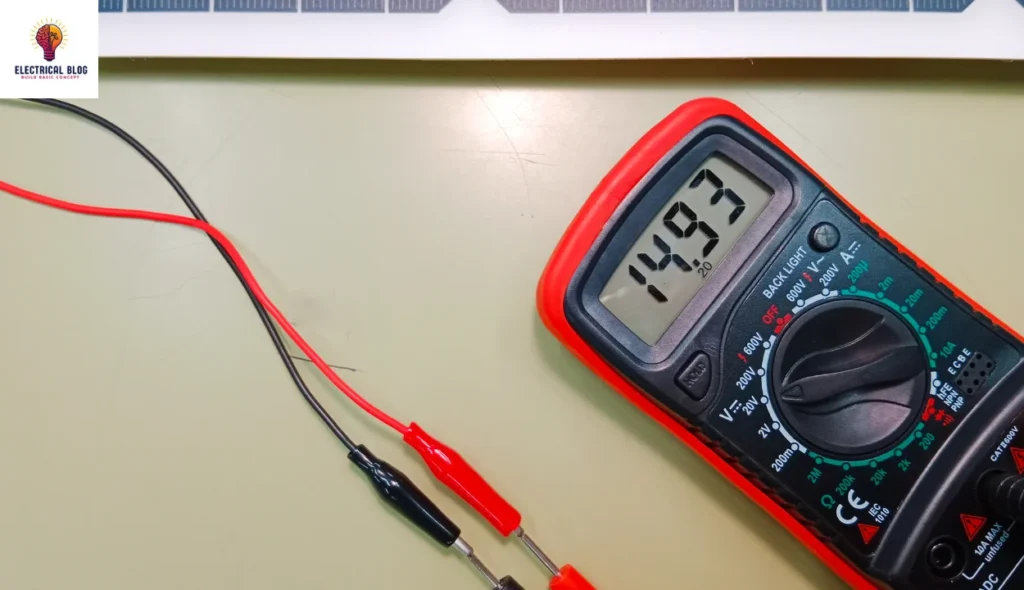
Measurement of DC voltage
It can be measured using a DC voltmeter or a multimeter.
To calculate the DC voltage, Ohm’s law can be used if the circuit current and resistance are known.
The values of circuit current and resistance can help determine the exact DC voltage in a circuit.
Conclusion
In this article, we have covered important concepts related to voltage and its measurement. It is used in many electronic circuits, where the magnitude can be either constant or time-varying. A multimeter is commonly used for measuring. Due to its simplicity it forces an electric current to flow in one direction, maintaining constant polarity. This makes it a key component in various applications.