Introduction
The capacitive voltage transformer (CVT) is an essential device in the electrical industry, offering a range of applications and benefits across multiple domains. Over the past decades, it has significantly evolved, driven by advancements in development and the need for more accurate voltage measurement solutions. With its working principle rooted in transformer technology, the CVT serves as a key tool for harmonic calculations, but it is also subject to certain regulations regarding its implementation.
This technology has gained credit over time, thanks to its reliability and ability to provide precise voltage transformation. Understanding its testing approach helps uncover its advantages, such as improved accuracy and efficiency in electrical systems. As capacitive voltage transformers continue to evolve, gaining deeper knowledge of their history and types reveals how this device remains a cornerstone in modern power systems.
What is a capacitive voltage transformer?
A capacitive voltage transformer (CVT) is a type of capacitive potential transformer that is designed to step down high-voltage input signals into manageable, low-voltage outputs that can be easily measured using a measuring instrument. This transformer consists of three main parts: a capacitive potential divider, an inductive element, and an auxiliary transformer. These components work together to ensure accurate voltage transformation and to provide safety in high-voltage systems. The capacitive potential divider plays a crucial role in the CVT’s operation, enabling precise voltage measurements while maintaining system integrity.
Why do we need a CVT?
The need for a CVT arises when dealing with high-voltage systems, especially those over 100 kV. In such systems, it is crucial to have a reliable method for measuring voltage without incurring the high costs associated with a highly insulated transformer, which can be quite expensive. Instead, a capacitive potential transformer is used as it offers a cheap solution while maintaining a performance that is not much inferior to its more costly counterpart. By reducing costs while still ensuring effective operation in the system, the CVT proves to be an excellent alternative to the normal transformer in certain high-voltage applications.
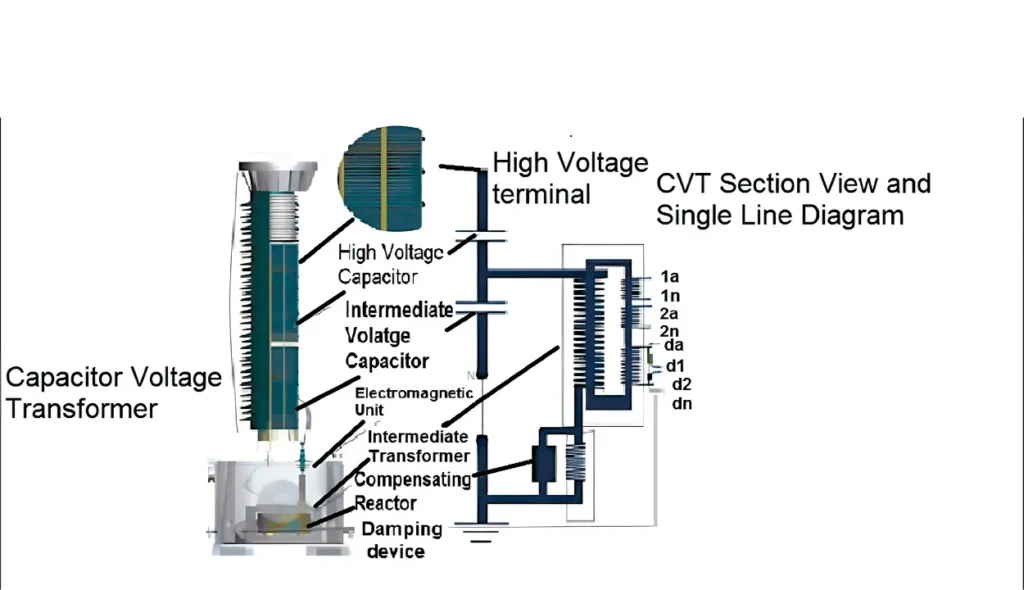
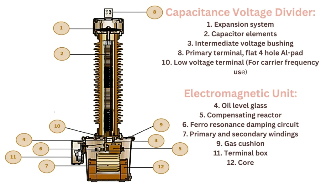
Capacitive Voltage Transformers Diagram
Capacitive Voltage Transformer Working
The capacitive potential divider works by reducing extra high voltage signals to manageable low voltage signals. It is made up of capacitors like C1 and C2 that are placed across transmission lines. The capacitor near the ground has a higher capacitance compared to the one near the line. This creates a step-down effect, reducing the high voltage to a lower, measurable output voltage.
The auxiliary transformer is an essential part of this system. After the capacitive potential divider, it takes the low-voltage signal and further steps down the voltage for accurate measurement. The primary winding and secondary winding of the transformer, with their turns ratios, play a key role here. The N1 and N2 indicate the number of turns in these windings, which help determine the voltage transformation ratio.
A circuit diagram illustrates how these components work together. The inductive element is included to prevent phase shift and compensate for voltage drops that happen due to current reduction from the divider. Additionally, adjustable inductances help control these voltage variations, though they are affected by inductance losses.
The voltage turn ratio can be expressed mathematically using C2/(C2 + C1) and N2/N1 to calculate how the voltage is transformed. The voltage transformation ratio is independent of the burden, meaning that the load on the secondary winding doesn’t affect the voltage measurement. This ensures that the output remains stable.
As for the operation, ω (angular frequency) is involved in the inductance calculation, and the values of V0 and V1 are linked to the capacitor values and turns ratio. With this setup, the system works efficiently to monitor and measure high-voltage systems, ensuring safety and accuracy in electrical distribution.
Difference Between the Capacitive Voltage Transformer and a Potential Transformer
In high-voltage systems, both CVT and potential transformer serve important roles, but they work in different ways. The CVT is an inexpensive solution compared to a potential transformer and is widely used in power line carrier communication and measurement applications. Below is a simple comparison:
| Feature | Capacitive Voltage Transformer (CVT) | Potential Transformer |
|---|---|---|
| Design | Uses a stack of capacitors in series to form a voltage dividing capacitor, followed by an inductive step-down transformer. | Built with a core and winding, following a simple design for direct voltage scaling. |
| Function | Provides a tuning advantage by making use of its capacitance, which allows for resonance at the basic frequency line. Also, it is tuned for power line carrier communication. | Works through electromagnetic induction and is primarily used for voltage protection and measurement. |
| Size & Cost | More economical, lighter design, and smaller in size, making it easier to install in high-voltage networks like 230KV to 12KV systems. | Requires a larger core, making it bulkier and more expensive due to core loss. |
| Performance | Can handle high-voltage transmission while reducing inductive fire back, improving efficiency. However, it is influenced by environmental factors. | More stable for precise voltage calculation but lacks a tuning advantage for high-frequency applications. |
A CVT is often preferred for high-voltage transmission systems due to its economical design, tuned nature, and capability to support power line carrier communication. However, when voltage protection is the main concern, a potential transformer is a better choice.
Conclusion
The Capacitive Voltage Transformer (CVT) is an essential device in high-voltage networks, offering an inexpensive and economical alternative to traditional transformers. Its design, which includes a stack of capacitors in series with a voltage-dividing capacitor and an inductive step-down transformer, allows it to efficiently step down high voltages like 230 kV to 12 kV for measurement, voltage calculation, and voltage protection.
A key advantage of the Capacitive Voltage Transformer is its tuning advantage, which makes it ideal for power line carrier communication, ensuring stable operation at the basic frequency line while being tuned to minimize inductive fireback. Additionally, its lighter design and smaller size reduce core loss, making it a practical choice for modern electrical grids that require precise and reliable voltage monitoring.