Introduction
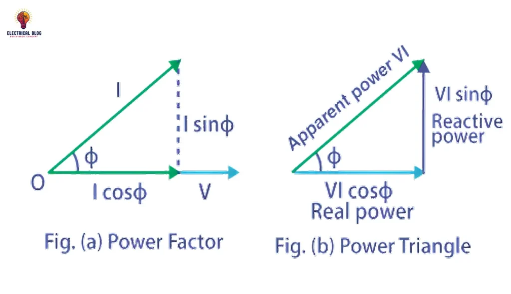
In my experience, power factor plays a critical role in determining the energy efficiency of electrical systems. It is essentially the ratio between working power (measured in kilowatts, or kW) and apparent power (measured in kilovolt-amperes, or kVA). This relationship demonstrates how effectively power usage is managed within a circuit. For instance, a 96% power factor means a highly efficient system, while anything below 95% is typically considered inefficient in many regions.
To put it simply, the power used to operate machinery and other equipment is directly affected by voltage (V) and current (A). By multiplying these two values, the apparent power is found and expressed in kVA units. A power factor closer to 1 ensures that less power is wasted, reducing demand on the system. For example, a system operating at a 75% power factor would waste more energy compared to one operating at 96%. This balance between true power and apparent power is crucial for maintaining optimal efficiency over a certain period.
Understanding the Electric Power Formula
In my experience, understanding the electrical power formula is essential for making better decisions about how to manage energy in systems. The formula, P = V x I, represents the relationship between electrical current (I), voltage (V), and total electrical power (P). This formula provides the foundation for understanding how real power is consumed, measured, and delivered by devices, making it a critical step before learning about the power factor.
By grasping the connections between measurements like current and voltage, teams can easily calculate and relate the ratio of real power to apparent power. This order of learning ensures that teams can move forward with confidence, improving their efficiency and knowledge. Following this best practice can significantly increase their ability to understand how electrical measurements work in harmony and why the power factor is so important.
How to Make Sense of Power Factor
Understanding power factor becomes easier with relatable analogies, like comparing it to a glass of beer. The useful power in a system is like the liquid beer, which does the real work (measured in kW). On the other hand, the foam represents reactive power (kVAR), or lost power that doesn’t contribute to useful output, such as energy wasted as heat or vibrations.
The mug itself symbolizes apparent power (kVA), which is the total demand power delivered by the utility. If there’s a difference between the demand and the available supply, it puts a strain on the system, often leading to extra surcharges or penalizing larger customers for inefficiency.
When peak demand occurs, utilities face challenges in maintaining a consistent supply due to irregular reserve capacity and load requirements. For example, AC circuits often experience inefficiency because of impedance in the power lines, leading to a lower power factor. This inefficiency increases costs, much like driving a gas-guzzling car.
Utilities often calculate charges based on the average load within 15 minutes or 30 minutes, and any overutilization during constant or highest demand periods leads to higher bills. Optimizing the power factor helps ensure efficient operations and avoids unnecessary penalties.
How to Calculate Power Factor
To calculate power factor, you need tools like a power quality analyzer or a power analyzer to measure both working power (kW) and apparent power (kVA). Using the formula
PF = W/VA
You can find the ratio of useful power (W) to the supplied power (VA). A low power factor indicates that true power is being inefficiently consumed, which can result in penalties and higher utility bills. Poor power factor can lead to strain on the system, increasing the cost of power distribution due to the need for higher current to supply loads.
An inefficient power factor can cause issues like heat damage to insulation and other circuit components, along with the need for larger equipment sizes and conductors. By improving the power factor through correction measures, businesses can achieve significant cost savings and enhance the efficiency of their electrical systems. A better power factor reduces the reduction in available useful power and minimizes the strain on the infrastructure, leading to a more reliable power distribution system.
Importance of the power factor in distribution systems
A power factor close to unity is essential for ensuring the efficiency of power transmission in modern distribution systems. For example, a low power factor of 0.7 means that apparent power is 1.4 times greater than the real power used, which increases transmission costs and results in proportional losses in the circuit.
This inefficiency requires larger transformers, conductors, and switchgear, increasing the overall size and cost of the system. For commercial customers, utilities often impose penalties if their power factor drops below 0.9, driving the need for correction measures to avoid additional expenses.
To meet energy standards like Energy Star and comply with guidelines such as EN 61000-3-2, consumer products and consumer electronics now use active PFC in their power supplies. Companies like Intel and organizations such as the U.S. Environmental Protection Agency emphasize the use of internal power supplies with a power factor of ≥ 0.9 to enhance efficiency and reduce rising costs of energy.
While households and small customers are not typically charged for reactive power, improved metering equipment and better supply management can help reduce unnecessary demand and ensure smoother power transmission for all.
Measurement Techniques of Power Factor
Measuring power factor in circuits involves several techniques. The wattmeter-ammeter-voltmeter method is often used in a balanced polyphase circuit to divide the power in watts by the product of voltage and current. In unbalanced polyphase circuits, measurements become less straightforward due to variations.
A moving coil meter, connected to the circuit load, uses a resistor and an inductor to measure delayed current and determine torque. The instrument pointer moves toward the 1.0 mark at unity power factor, while at zero power factor, another coil creates the torque to show minimal efficiency.
Modern digital instruments calculate apparent power, true power, and total harmonic distortion more precisely. They measure the time lag between voltage sources and current to account for sinusoidal waveforms or even distorted waveforms. Standards like IEC61000-3-12 and IEC61000-3-3 help regulate harmonic measurement and flicker measurement. For single-phase systems, a phase-shifting reactor may be used, while advanced devices can measure individual voltage and current harmonics.
Whether measuring DC voltage, DC current, or AC voltage, these tools ensure accurate analysis of circuit current flow and amplitude for both balanced and unbalanced systems.
Read more: Power Triangle


