Introduction
Overview of Electrical Cable Sizing
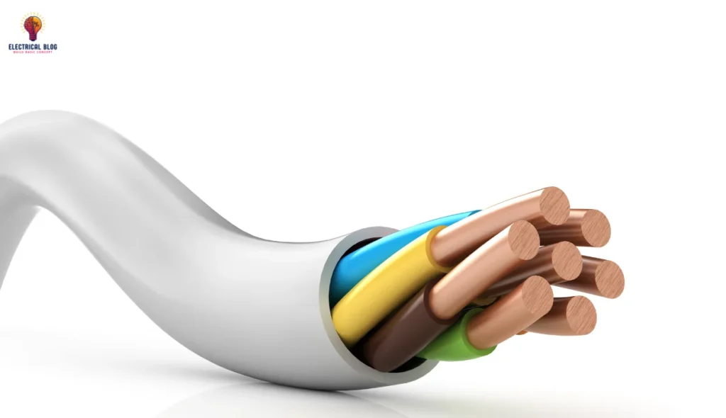
Choosing the right size for electrical cables is key in system design. It ensures cables carry current safely without overheating or failing. This sizing process considers current capacity, voltage drop, and short-circuit limits. Proper sizing is vital for the safety and integrity of the electrical system.
Importance of Accurate Cable Sizing in Electrical Systems
Choosing the right cable size is vital for safety and efficiency in electrical work. Cables that are too small can overheat, leading to damage or even fires. Cables that are too large can cause extra costs and become unreliable. Ideally sized cables manage the load, reduce voltage drop, and endure short circuits. This prevents failures and helps meet industry standards.
Purpose and Scope of the Article
This article helps you size electrical cables. It covers calculations, selection factors, and tips. You’ll learn about current capacity, voltage drop, and short-circuit needs. By the end, you’ll know how to choose a cable for safety, efficiency, and compliance.
Understanding the Basics of Cable Sizing
Definition and Key Concepts: Cable sizing is finding the right cable size.It must consider:
- current-carrying capacity
- voltage drop
- short-circuit withstand
- environmental factors
Types of Electrical Cables:
Low Voltage: For residential and commercial use, usually up to 1,000 volts.
Medium Voltage: * Used in industrial applications at 1,000 to 35,000 volts.
High Voltage: For long-distance power transmission, use over 35,000 volts.
Overview of Cable Materials:
Copper vs. Aluminum: Copper is better. It’s more conductive and reliable. Aluminum is lighter and cheaper.
Insulation Types: Common materials include PVC, XLPE, and rubber. Each one suits different environments and voltage levels.

Factors Influencing Cable Sizing
Choosing the right cable size involves several factors. It functions flawlessly across diverse scenarios with stable safeguards. Here’s an overview of the key factors:
Operating Current
Continuous Current Rating: A cable’s continuous current rating is the maximum current it can carry without overheating in normal conditions. It depends on the cable’s size, insulation type, and the surrounding environment. Exceeding this rating can cause overheating. It may degrade the cable’s insulation and performance.
Load Types and Characteristics: Resistive, inductive, and capacitive loads affect a cable’s current. Inductive loads, like motors and transformers, can cause high inrush currents. Thus, understanding these loads is key. It helps in choosing a cable that can handle both normal and surge currents.
Voltage Drop Considerations
Importance of Minimizing Voltage Drop: Voltage drop is the loss of voltage as electricity travels along the cable. Excessive voltage reduces equipment performance and increases energy loss. So, choosing the right cable size is vital. This ensures that equipment gets the right voltage for the best performance.
Calculating Voltage Drop in AC and DC Circuits:
AC Circuits: In AC circuits, the voltage drop depends on the cable’s resistance, reactance, and current frequency. The formula for voltage drop in AC circuits includes both resistance and reactance.
- For AC systems, the voltage drop (
) is calculated as:
DC Circuits: In DC circuits, the voltage drop is easier to calculate. Cable resistance and length govern the outcome. The formula is straightforward: Voltage Drop = Current / Resistance / Length.
- For DC systems, the calculation simplifies to:
Short Circuit Conditions
Circuit points merge, sidestepping the load, to create a short circuit. It’s important to know this. This causes a sudden current surge. Design cables to handle high currents safely. This prevents fires and ensures safety.
Calculating Short Circuit Currents: This finds the maximum fault current in the system. This depends on the system’s impedance and the supply characteristics. Engineers use standard formulas and software tools to estimate these currents.
Cable Sizing for Short Circuit Withstand: Cables must handle the normal current. They must also withstand the thermal and mechanical stresses of short-circuit conditions. This often requires using higher-rated cables and heat-resistant materials.
Environmental and Installation Factors
Ambient Temperature: The environment’s temperature affects the cable’s capacity. Higher ambient temperatures can limit the cable’s ability to dissipate heat. This requires larger cables or derating their capacity.
Installation Methods:
Buried: Underground cables dissipate heat differently than those in open air. Factors like soil thermal resistivity and depth of burial impact heat dissipation.
Conductor: Cables in conduits can’t dissipate heat as well as those in the air. This limits their current carrying capacity.
Air: Cables in open air can dissipate heat better. They can usually carry more current than those in confined spaces.
Impact of altitude and humidity:
Altitude: At high altitudes, the air density drops. This can reduce the cable’s ability to dissipate heat. This may require adjusting the cable size or derating its capacity.
Humidity: High humidity can harm insulation and cable performance. We may need to choose cables with moisture-resistant insulation.
Standards and Regulations
Selecting the right cable size and ensuring its safe use involves adherence to various standards and regulations. Here’s an overview of the key standards and codes relevant to cable sizing:
Overview of International Standards
International Electrotechnical Commission (IEC): The IEC sets global standards for electrical and electronic technologies, including cable size. Some key IEC standards related to cable sizing are:
IEC 60502-1: It covers specifications for power cables with extruded insulation for 1 kV to 36 kV. It includes guidelines on construction, performance, and testing.
IEC 60364-5-52: This part of the IEC 60364 series. It provides requirements for selecting and installing electrical cables and conductors in buildings. It addresses factors like current carrying capacity and installation conditions.
National Electrical Code (NEC): The NFPA developed the NEC. It is widely used in the U.S. It details requirements for electrical installations, including cable sizing. Relevant sections include:
NEC Article 310: It covers the conductors for electrical installations. It includes cable size, insulation types, and installation methods.
NEC Article 300: It covers wiring methods and materials. It affects cable installation practices.
National and Local Codes and Compliance
National Codes: They set rules for each country. They ensure safety and reliability in electrical work. For example:
BS 7671 (UK): The IET Wiring Regulations. They set standards for electrical installations in the UK. This includes cable sizing and installation practices.
AS/NZS 3000 (Australia/New Zealand): The Australian/New Zealand Wiring Rules. It has guidelines for electrical installations in these regions.
Local Codes: Local codes may refine national or international standards. They do this to meet specific regional needs or conditions. These codes are vital. They ensure safety and meet local laws.
Specific Standards for Cable Sizing
IEC 60502-1: This standard specifies the requirements for medium voltage power cables (up to 36 kV) with extruded insulation. It covers:
Construction: Specifications for cable materials and design.
Performance: Guidelines for electrical and mechanical tests. They include tests for short-circuit resistance and thermal properties.
IEC 60364-5-52 Part of the broader IEC 60364 series, this standard focuses on the selection and installation of cables in buildings. It includes:
Current Carrying Capacity: Guidelines for selecting the right cable size based on load and installation conditions.
Installation Conditions: Requirements for cable installation methods and environments. They ensure safe and effective performance.
NEC Article 310: It provides guidelines on choosing conductors for electrical systems. It addresses:
Temperature Ratings: Considerations for conductor insulation based on ambient temperatures.
Ampacity: Tables and formulas for calculating the maximum current a conductor can handle.
Cable Sizing Calculations
Accurate cable sizing requires precise calculations to ensure safety and efficiency. Here’s a guide on the calculations to find the right cable size.
Calculating Current Carrying Capacity
Formula and Example Calculations: Several factors determine a cable’s ampacity. They are its cross-sectional area, insulation type, and installation conditions.
The basic formula for calculating the current carrying capacity is:
Where:
I = Current (amperes)
P = Power (watts)
V = Voltage (volts)
Power Factor = Efficiency of the Electrical System (between 0 and 1)
Example Calculation: We need to find the cable’s capacity. It carries 15,000 watts at 230 volts with a 0.9 power factor.

Application of Derating Factors
Derating Factors: They account for conditions that affect cable performance. These include ambient temperature and installation methods.
Temperature:
Ambient Temperature: Higher temperatures can reduce the cable’s current carrying capacity. For example, if the standard rating is 100 A at 30°C and the ambient temperature is 40°C, you may need to derate the capacity using a correction factor (e.g., 0.8 for 40°C).
Iadjusted=I×Derating Factor
For instance, if the cable’s temperature rating is 30°C, and it’s operating in an environment at 40°C with a derating factor of 0.8:
Installation:
Buried: Cables buried in the ground may need derating. They dissipate less heat than those installed in air.
Conduit: Cables in conduit also need derating, as heat dissipation is limited.
Adjusted Current Carrying Capacity: For a 40°C ambient temperature and a derating factor of 0.8, it is:
Adjusted Capacity = 48.5 x 0.8 = 38.8 amperes
Voltage Drop Calculations
Voltage drop calculation ensures that the load receives an acceptable voltage. The formula for voltage drop is:
Voltage Drop = I, R, L
Where:
I = Current (amperes)
R = resistance per unit length of the cable (ohms per meter).
L = length of the cable (meters)
For AC circuits, the formula includes reactance:
Voltage Drop = I × (R + jX) × L
Where:
X = Reactance (ohms per meter)
j = imaginary unit
Example Calculation for DC Circuit: Assume a cable length of 100 meters. The current is 10 amperes, and the resistance is 0.5 ohms per kilometer.
Convert resistance to ohms per meter:
Resistance = 0.5 / 1,000 = 0.0005 ohms per meter.
Voltage Drop = 10 × 0.0005 × 100 = 0.5 Volts
Example Calculation for AC Circuit: For an AC circuit with reactance:
10 Amperes
Resistance: 0.5 ohms
Reactance: 0.3 Ohms
Length: 100 meters
Calculate impedance: Z = R2 + X2 = 0.5+ 0.3 = 0.583
Z = R + X = 0.5 + 0.3 = 0.583
Voltage Drop = 10 × 0.583 × 100 = 583 volts.
Short Circuit Capacity Calculations
Method for Determining Short Circuit Withstand: Short-circuit calculations check whether cables can endure high fault currents without damage.
Determine Fault Current: Use system parameters and fault tools to find the maximum short-circuit current. This often involves complex calculations or software tools based on system impedance.
Calculate thermal and mechanical stresses: short-circuit currents stress the cable. They cause thermal and mechanical effects. The cable must be sized to withstand these stresses for a short duration without damage.
Example calculations based on cable material and cross-section: Assume a 10,000 A short-circuit current and a 25 mm cable.
Calculate thermal stress: Use manufacturer data or standards. They will determine the cable’s short-circuit withstand capability. For example, a cable may need to withstand 10,000 amperes for 1 second without damage.
Check the cable’s short-circuit rating in the specs or standards. It must meet the requirements. For instance, a 25 mm copper cable may be rated to handle 10,000 amperes for 1 second.
Practical Considerations in Cable Sizing
When selecting cables for electrical systems, practical concerns are key. They balance performance, safety, and cost. Here’s an overview of these considerations:
Cost vs. Performance Trade-Offs
Balancing Budget with System Requirements: Choose the right cable. It must balance cost and performance. Higher-performance cables, like those with better insulation or larger areas, cost more. It’s essential to consider:
Initial Cost: Higher-capacity or specialized cables may be more expensive upfront.
Operational Efficiency: Better performance can cut costs. It reduces energy loss and maintenance issues.
Material Selection: Copper vs. Aluminum:
Copper: Its high conductivity makes copper cables the best. They are more reliable and perform better. They are preferred where space is tight or performance is critical. However, they are more expensive than aluminum.
Aluminum: Aluminum cables are cheap and light. They suit large, cost-sensitive, weight-sensitive installations. Their resistance is higher than copper’s. This may require larger sizes to handle the same current.
Cost considerations: Aluminum cables can cut initial costs. But their higher resistance may cause energy losses over time. Considering the total lifecycle cost, including maintenance, helps in making a good decision. It includes efficiency.
Safety Considerations
Overheating risks and preventative measures: Overheating is a major risk in cable installations. It can damage insulation, cause electrical fires, or lead to system failures. Preventive measures include:
Proper Sizing: The cable must be sized for the load to avoid overheating.
Cooling: Ventilate and cool, especially for cables in confined spaces or conduits.
Regular Inspections: Routine checks for signs of overheating, damage, or wear.
Case Studies and Practical Examples
Real-world examples can show how to apply cable sizing. They can help us understand their theories in different settings. Detailed case studies are available for different types of installations.
Industrial Installation Example
Detailed cable sizing process for an industrial facility:
Scenario: An industrial facility requires cables for power distribution, lighting, and machinery. The facility includes several large motors, transformers, and other high-power equipment.
Determine load requirements:
Load Analysis: To find the total load, sum the power needs of all equipment and machinery. For example, suppose the total power requirement is 500 kW.
For a 500 kW load at 400 V (three-phase) with a 0.9 power factor:
I = P / (3 × V / Power Factor)
I = 500,000 / (3 / 400 / 0.9) / 721 amperes.
Cable Sizing:
Choose Cable Type: For industrial use, XLPE-insulated cables are the best. They have good thermal and electrical properties.
Select Cable Size: Use standard tables or software to select a cable size that can handle 721 amps. For example, a 300 mm copper cable might be suitable. Standard ratings and derating factors form the basis for this.
Consider derating factors:
Temperature: If the ambient temperature is higher than 30°C, apply a derating factor (e.g., 0.8 for 40°C).
Installation Method: If cables are in a poorly ventilated conduit, apply additional derating.
Verify Voltage Drop:
Ensure that the voltage drop is within acceptable limits. For a 100-meter run, calculate the voltage drop. It must not exceed the maximum allowable value.
Short Circuit Capacity:
Check the cable’s short-circuit withstand capacity. It must handle potential fault currents.
Commercial Building Example
Cable Sizing for a Large Commercial Office Building:
A large office building needs cabling for its lighting, HVAC, and power systems.
Determine load requirements:
Load Analysis: Suppose the total connected load is 200 kW.
For a 200 kW load at 230 V (single-phase) with a 0.9 power factor:
I = 200,000 / (230 / 0.9) / 1,211 A.
Cable Sizing:
Choose Cable Type: Use PVC or XLPE-insulated cables, depending on installation conditions.
Select Cable Size: Based on the current, a 500 mm aluminum cable may work. But verify with standard tables or software.
Consider derating factors:
Temperature and Installation: Derate for ambient temperature and for installation methods, such as in raised-floor or ceiling spaces.
Verify Voltage Drop:
Calculate the cable runs’ voltage drop. It must be within limits.
Safety and Compliance:
Ensure the selected cables meet local building codes and safety standards.

Renewable Energy Installation Example
Special Considerations for Cable Sizing in Solar and Wind Power Systems:
While simplifying, balance brevity with important nuances. Ensure a smooth flow by connecting ideas. Retain key style or vivid imagery if it aids clarity and engagement.
Install cables for a solar power system. It has PV panels and inverters.
Determine load requirements:
PV System Output: Suppose the total system output is 50 kW.
For a 50 kW solar array at 600 V DC:
I = 50,000 / 600 = 83.3 amperes.
Cable Sizing:
Choose Cable Type: Use UV-resistant and weatherproof cables suitable for outdoor use. In solar applications, people prefer cables with double insulation (such as PV cables).
Select Cable Size: For 83.3 amps, a 10 mm cable may work. But check the manufacturer’s standards.
Consider derating factors:
Temperature: PV cables must be rated for high temperatures and UV exposure.
Environmental factors: Cables must resist moisture and outdoor conditions.
Voltage Drop:
In DC systems, minimize voltage drop over long distances to maintain efficiency. For a 100-meter run, calculate and verify that the voltage drop is acceptable.
Safety and Compliance:
Cables must meet standards for renewable energy installations. These include ISO 61730 for solar panels and ISO 60228 for cables.
Tools and Resources for Cable Sizing
Cable Sizing Software
Using cable sizing software can simplify the process and ensure accuracy. Popular tools include ETAP, CYME, and AmpCalc. These tools can do complex calculations. They also auto-derate based on installation conditions.
Key Tables for Quick Reference
Current carrying capacity
A cable’s ampacity is its maximum current limit without overheating. This limit depends on the cable’s size, material, insulation, and installation conditions.
| Conductor Size (mm²) | Copper Cable (A) | Aluminum Cable (A) | Installation Method (Air, Conduit, Buried) |
|---|---|---|---|
| 1.5 | 18 | 15 | Air |
| 2.5 | 24 | 20 | Conduit |
| 4 | 32 | 26 | Buried |
| 6 | 40 | 34 | Air |
| 10 | 55 | 45 | Conduit |
| 16 | 75 | 60 | Buried |
Voltage Drop
Voltage drop happens when voltage decreases in a circuit, from the source to the load. Keeping it within limits is vital for the proper functioning of electrical equipment.
| Conductor Size (mm²) | Voltage Drop (V/m) | Current (A) | Length (m) | Material (Copper/Aluminum) |
|---|
| 1.5 | 29.0 | 10 | 20 | Copper |
| 2.5 | 18.0 | 20 | 25 | Aluminum |
| 4 | 11.5 | 30 | 30 | Copper |
| 6 | 7.8 | 40 | 40 | Aluminum |
| 10 | 4.6 | 50 | 50 | Copper |
Derating Factors
Derating factors adjust a cable’s current capacity based on environmental conditions. These include temperature, cable grouping, and the installation method. These factors ensure that cables operate safely and efficiently under different conditions.
| Ambient Temperature (°C) | Derating Factor (Copper Cable) | Derating Factor (Aluminum Cable) |
|---|---|---|
| 20 | 1.08 | 1.07 |
| 30 | 1.00 | 1.00 |
| 40 | 0.94 | 0.93 |
| 50 | 0.88 | 0.87 |
| 60 | 0.82 | 0.81 |
Common Mistakes in Cable Sizing
Avoid these common pitfalls in cable sizing:
Misjudging current requirements: Always consider the worst-case scenario.
Ignoring environmental factors: Don’t ignore the effects of temperature, humidity, and installation conditions.
Overlooking Voltage Drop and Short Circuit Capacities: Ensure all calculations meet standards. They must be thorough.
Skipping Compliance with Standards: Adherence to standards like IEC and NEC is non-negotiable.
Conclusion
Choosing the right electrical cable is crucial and complex. It involves considering factors like current capacity, voltage drop, and short-circuit risks. Engineers should follow standards and use accurate data. This ensures cables perform safely, efficiently, and reliably in any installation.


