Introduction
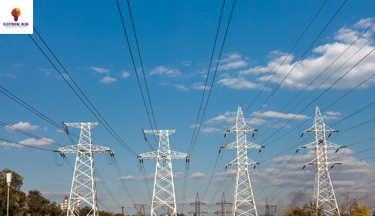
Growing up, I was always fascinated by the tall metal towers stretching across landscapes, carrying high-voltage current between power plants and substations. These structures play a key role in delivering electricity across the grid, ensuring every region gets a stable supply. Made from steel, concrete, or even ductile iron, they must withstand extreme temperature changes and external forces. Whether wooden distribution poles in neighborhoods or massive pylons spanning natural chasms, each serves a crucial function.
The height of these electrical transmission towers varies based on their location, with some standing 50 feet to 150 feet, and special cases reaching 1,247 feet (380 m) to span waterways. Their design ensures safety by keeping power lines at a secure length, preventing contact with objects, vehicles, or people. Insulators help support conductors, minimizing sag caused by tensile forces. The mechanical properties of these wires depend on voltage, pre-tensioning, and environmental conditions.
These towers manage electricity from 23,000 volts to an impressive 765,000 volts, requiring well-planned circuit structures. Some areas rely on underground power lines where space is limited, but in open areas, towering bulk power transmission is preferred. Engineers carefully design them to balance weight, height, and environmental factors. Whether above cities or cutting across vast landscapes, these electrical giants remain an essential part of modern life.
What is a transmission tower?
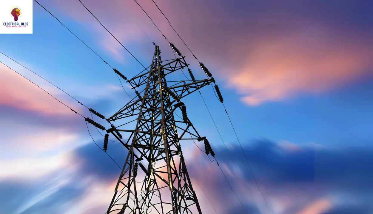
A transmission pylon is a tall structure built to carry high-voltage transmission lines across vast distances. These towers ensure electricity moves from generating stations to substations before reaching electric customers. Made of steel lattice, they must withstand harsh weather and natural disasters to function safely.
Engineers focus on designing towers that efficiently support heavy conductors while keeping power flowing. In an electrical grid, towers handle bulk energy transfer and help with sub-transmission and distribution lines. Utility poles manage lower-voltage power, keeping neighborhoods connected.
A crucial part of engineering, these towers require civil, mechanical, and electrical expertise. The task of integrating them into grids ensures steady power transport. Proper planning keeps them standing safely above roads and fields, making reliable power delivery possible.
Role of Transmission Tower Conductors
The conductors in electrical transmission towers play a vital role in delivering electricity over long distances. These are often steel-reinforced and made of aluminum conductor steel-reinforced (ACSR) for durability. Arranged in sets, they handle three-phase alternating current efficiently. Each conductor line follows a specific grouping, either in a triangular shape or laid out parallel to each other.
Typically, towers hold one conductor line per phase, making it three total, but some use multiple lines per group. This setup increases efficiency, especially over short distances, ensuring power is delivered safely. At the top of the towers, overhead wires like ground wire, static wire, or pilot wire help protect against lightning. These wires absorb strikes and deflect them to the ground.
Another key feature is the use of fiber-optic cables, which are often placed below the main conductors. Since glass cannot conduct electricity, these cables are not affected by power flow. Adding them to networks provides a return on investment, as they support telecommunication services. Utility providers may operate them directly or have them leased to cable companies and phone companies.
In some cases, fiber optics are placed just a few feet beneath the conductor lines to optimize space. Their voltage potential is zero under normal conditions, making them ideal for communication. These additions allow telecommunication companies to expand their reach while using existing utility infrastructure. By integrating power and data transmission, modern grids become more efficient and sustainable.
Electrical transmission towers
Types of Transmission Tower Structures
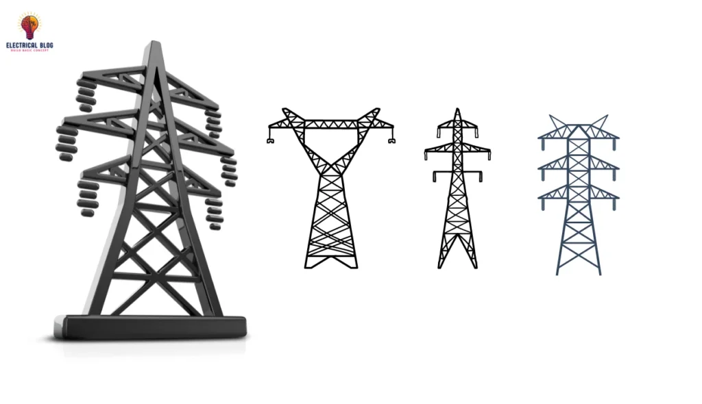
Electrical transmission towers come in lattice type and pole type designs, each suited for different voltages and transmission distances. Lattice steel towers, built from steel angle sections, are ideal for higher voltage levels, while wood pole towers are used economically for short spans. Some towers are self-supporting, while others are guyed with cables for stability. The configuration of a transmission line tower depends on multiple factors that influence safety and efficiency.
Configuration of a transmission line tower depends on:
Number and type of conductors used.
Insulator assembly length affects minimum clearances.
Distance is maintained between the conductors and the tower.
Mid-span clearance for dynamic behavior and lightning protection.
Placement of the ground wire near the outermost conductor.
Minimum clearance of the lowest conductor above the ground.
Factors Governing the Height of a Tower:
Minimum permissible ground clearance (h1) to ensure safety.
Maximum sag (h2) of conductors due to weather conditions.
Vertical spacing (h3) between the top and bottom conductors.
Vertical clearance (h4) between the top conductor and the ground wire.
The total height of the tower is determined by the sum of all these factors (h1 + h2 + h3 + h4).
Tower Configuration
The configuration of a transmission line tower depends on various factors that impact safety, performance, and cost. Towers must withstand mechanical loads from different directions, whether straight or at an angle. For high voltages like 500 kV and above, conductors are often bundled to minimize corona emissions and line inductance.
Configuration of a transmission line tower depends on:
Number of circuits in the transmission system.
Single-circuit or multi-circuit design selection.
Placement of conductors in horizontal or vertical structures.
Choice of V strings or other support configurations.
Selection of tower sites for stability and durability.
Consideration of the future addition of new circuits.
Selection of rigid points for strong structural integrity.
Proper selection of insulators to handle voltage loads.
Selection of conductor configurations to optimize performance.
Maintaining an economy in tower design for lower costs and maintenance is essential.
Towers are classified by use, independent of the number of conductors they support. Engineers work to simplify designs by using standard types, ensuring durability while reducing construction time and expenses.
Transmission Tower Types
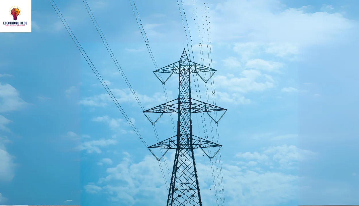
Different towers are designed to handle conductors and support transmission lines efficiently. Suspension towers hold conductors in a straight path, while strain towers manage changes in direction or loading.
Tension towers are placed at relative points to handle the axial strain caused by the weight of the cables. At the substation, conductors may be routed underground via cable or continue overhead.
A transposition tower adjusts the position of conductors to balance electrical flow. The tower’s insulators help maintain a safe distance between each wire and prevent electrical faults.
In some cases, terminal towers are used where the line ends or changes direction. These towers are essential for managing electrical flow and keeping the transmission system stable.
Tangent towers
Different towers are used in the transmission system based on their purpose and ability to withstand external forces. Tangent towers are the most common type, making up ninety percent of the lines that traverse flat, featureless terrain. Designed by engineers to minimize weight, they use steel and a strong design to resist wind, ice, and broken conductor loads.
Angle towers
For areas where the line needs to change direction, angle towers or semi-anchor towers are used. They must resist transverse forces and handle deviation angles from 2-10°, 10-30°, or 30-60°. These towers are heavier by necessity to support the extra loads. Large, medium, and small angle towers are classified based on their ability to manage direction changes.
Strain towers
Strain towers handle tension by using strain insulators to resist the net axial forces caused by the conductors. These towers prevent excessive loading on the structure by ensuring forces are properly placed and balanced. Unlike suspension towers, strain towers must be built to support the acting transmission loads.
Dead-end towers
At the end of a transmission line, dead-end towers or anchor towers are installed to support the weight of the conductors. These towers cater to high tension and are placed periodically to prevent cascade failures when a conductor fails. In some cases, they connect to a substation or transition to underground lines.
Transmission Tower Loads
An electrical transmission tower must handle numerous loads to stay stable. The dead load includes the weight of the tower, conductors, and other equipment. External forces such as wind load, snow, and ice add to the strain. Seismic activity, including earthquakes, can also impact the transmission tower. Engineers use wind load calculations and weight span methods to ensure safety.
The impact of wind directions and maximum wind velocity must be taken into account. The wind force can vary across the entire span, affecting the electrical transmission towers. Factors like climate, local conditions, and exposure to extreme weather can increase stress. Underestimation of these factors has led to collapses in the past. Load calculations help in determining the necessary strength of the structure.
Tensile forces in conductors also play a crucial role in tower stability. Longitudinal forces act on two faces of the tower in the line direction. If forces are balanced, suspension towers remain stable, but terminal towers and angle towers face heavy longitudinal resultant forces. Engineers use the angle bisector plane method to manage these forces and prevent failures.
Loads Acting Upon a Transmission Tower:
Dead load from the tower, conductors, and equipment.
Wind load affects the tower and conductors.
Seismic activity and earthquakes are causing structural stress.
Ice and snow are increasing the weight and wind effects.
Wind load calculation using wind span and pressure analysis.
Weight span method for balancing loads.
Load calculations to prevent collapse.
Longitudinal forces affect angle towers and terminal towers.
Resultant force acting in the angle bisector’s plane.
Conclusion
Electrical transmission towers play a crucial role in delivering electricity safely across long distances. These towers must withstand various loads, including wind loads, snow, ice, and seismic activity, such as earthquakes. Engineers use wind load calculations, weight span methods, and load calculations to ensure stability.
Different tower types, such as suspension towers, angle towers, and dead-end towers, are designed to handle specific forces. Tensile forces, longitudinal forces, and resultant forces affect their strength. Proper tower design, material selection, and maintenance are essential to prevent collapse and ensure reliability.
The configuration of a transmission line tower depends on factors like voltage, conductor arrangement, and environmental conditions. Engineers must take into account wind direction, climate, and local conditions. By implementing the right design strategies, electrical transmission towers can efficiently support the transmission system while minimizing costs and maximizing safety.

