Introduction
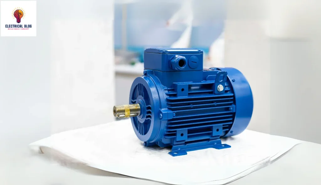
A 3-phase induction motor is a powerful device that performs electromechanical energy conversion, turning three-phase electrical power into mechanical output. It is widely used in industries because it runs on alternating current and does not need extra components to start, making it a self-starting machine. This motor consists of two main parts: a stator and a rotor, where the stator carries the main winding, and the rotor contains a short-circuited winding. The supply to the stator creates a magnetic field, which induces current in the rotor through electromagnetic principles.
Its construction is simple, yet its working relies on well-defined mechanisms that make it reliable. Various applications include industries, household appliances, and electric vehicles, showcasing its adaptability. The advantages of this motor are its efficiency and durability, while its disadvantages may involve maintenance of its winding system. Understanding its principles helps engineers and manufacturers optimize its performance for various needs.
What is a 3-phase induction motor?
A three-phase induction motor is an AC-type machine that runs efficiently on a supply of three-phase currents. Unlike a single-phase motor, which needs extra components to start, this motor generates an electromagnetic field naturally. The stator carries the main winding, and the rotor interacts with the magnetic force to produce torque. This design makes it reliable and widely used in industrial and commercial applications.
3-phase induction motor diagram

Construction of 3-Phase Induction Motor
A three-phase induction motor is a type of three-phase motor consists of a stator and a rotor, separated by an air gap ranging from 0.5 mm to 4 mm, depending on the power rating. The stator holds the stationary winding, while the rotor rotates inside it, generating motion. Its construction is designed for efficiency and durability in various applications.
Stator of 3-Phase Induction Motor
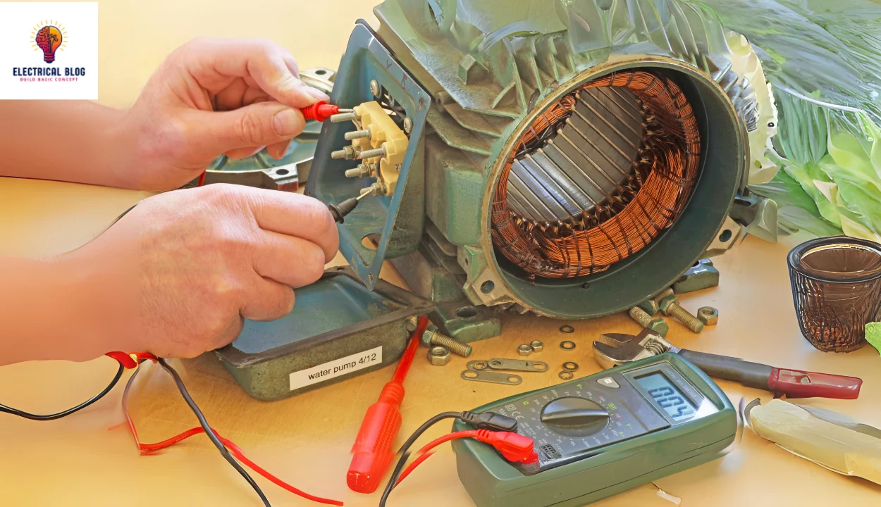
The stator is the stationary part of the motor, designed with a steel frame that encloses a hollow cylindrical core. This core is made of silicon steel lamination with thin layers to reduce hysteresis losses and eddy current effects. It has evenly spaced slots on the inner periphery of the laminated structure, where insulated conductors are placed. These stator slots hold the balanced 3-phase winding, which can be connected in a delta or star-connected configuration. The number of poles in the winding depends on the speed requirement, where a greater speed means fewer poles, and vice versa.
When a supply is given, a rotating magnetic flux (RMF) of constant magnitude is generated. This RMF interacts with the rotor and induces currents in its circuit through electromagnetic induction. This process ensures the smooth and efficient operation of the three-phase induction motor, making it highly reliable.
Rotor of a 3-Phase Induction Motor
The rotor of a 3-phase induction motor has a laminated core with a hollow cylindrical shape. It has slots on its outer periphery, where the rotor windings are placed. The winding placement determines its type, either a squirrel cage type or a wound slip-ring type rotor. These designs help the motor operate smoothly and efficiently in different applications.
Squirrel Cage Type Rotor
The squirrel cage rotor has a cylindrical laminated core with skewed slots on its outer periphery. These slots are nearly parallel to the shaft axis, holding uninsulated aluminum or copper bars as rotor conductors. At both ends, these rotor bar conductors are joined by heavy end rings, forming a short circuit. This structure creates an indestructible winding, as it remains permanently short-circuited. Its shape resembles a cage, similar to those used for squirrels, giving it its name.
Through electromagnetic induction, currents are generated in the rotor by the stator without a direct electrical supply. Squirrel cage induction motors are the most commonly used 3-phase induction motors in industries due to their simple and robust construction. They perform well in a versatile environment, making them ideal for various applications. However, they have a low starting torque, which can be a limitation in some cases.
To improve performance, the rotor slots are skewed, reducing noise and ensuring uniform torque during operation. This also minimizes the magnetic locking tendency, preventing cogging, which happens when the rotor and stator teeth lock together due to magnetic action. These design improvements make the squirrel cage rotor highly efficient and reliable.
Wound rotor or slip-ring rotor
The slip ring rotor has a laminated cylindrical armature core with slots on its outer periphery. Inside these slots, insulated conductors are arranged to form a 3-phase double-layer distributed winding, similar to the stator winding. The rotor conductors are connected to form rotor windings in a star configuration. The star connection has open ends that are connected to three insulated slip rings mounted on the rotor shaft. Brushes rest on these rings, allowing a connection to variable resistors arranged in a star configuration.
These external resistors help adjust the rotor circuit, making the equivalent circuit more flexible. The wound rotor offers advantages like reduced starting current from the supply and increased starting torque. It also allows speed control of the motor, making it suitable for applications requiring variable performance. This design makes the slip ring rotor a valuable alternative to the squirrel cage type.
Working Principle of a 3-Phase Induction Motor
A 3-phase induction motor works on the principle of electromagnetic induction, where an electromotive force is induced in the rotor. When a three-phase supply is given to the stator, a rotating magnetic field is created. This field moves anticlockwise, with moving polarities that change based on the positive half-cycle and negative half-cycle of the supply. The stator windings are evenly displaced at 120°, which ensures smooth rotation. Since the rotor conductors are stationary, they experience the effect of the rotating magnetic field.
Due to electromagnetic induction, the rotor-induced EMF is generated in the stationary conductor. Since the rotor windings are usually short-circuited, a current starts flowing through them. The relative motion between the rotor and the rotating magnetic field causes the rotor flux to develop. This flux interacts with the stator flux, leading to a force being exerted on the rotor conductors. The result is that the rotor starts moving in the same direction as the rotating magnetic field.
As the rotor begins to rotate, the high-density flux and low-density flux regions cause a push on the rotor conductor. This creates torque, specifically known as electromagnetic torque, which keeps the motor running. However, the speed of the rotor is always less than synchronous speed, as the rotor slips behind the rotating magnetic field. This small difference in speed is necessary for continuous induction to take place.
The end rings and external resistance play a crucial role in adjusting the rotor current and controlling the torque of the motor. If the rotor conductors were not short-circuited, the EMF generated would not produce any movement. The stator flux and rotor flux interact to maintain stable rotation. The ability of the motor to maintain torque under different loads makes it ideal for various applications.
Since the rotor never reaches synchronous speed, a 3-phase induction motor is also called an asynchronous motor. This ensures that the motor continues to work efficiently under varying loads. The magnetic field polarities shift continuously, maintaining a smooth rotation. This phenomenon makes the induction motor one of the most reliable and widely used electrical machines.
Types of 3-Phase Induction Motors
3-Phase Squirrel Cage Induction Motor
Slip ring or Wound Rotor Induction Motor
3-Phase Squirrel Cage Induction Motor
The squirrel cage induction motor gets its name because its rotor looks like a cage used for a squirrel. Its construction is simple and rough, making it highly durable. The cylindrical laminated core has slots on the outer periphery, which are skewed at an angle to prevent cogging. This design ensures smooth operation, reduces humming noise, and increases the length of the rotor conductor. The increased length also raises the rotor resistance, improving efficiency.
Instead of a rotor winding, the rotor bars are made of brass, copper, or aluminum, with end rings that short-circuit them permanently. This creates a fully closed path in the rotor circuit and provides mechanical support through welded joints. Since the rotor bars are short-circuited, adding external resistance is not possible. The simpler and more robust design eliminates the need for slip rings and brushes, making the motor highly reliable and maintenance-free.
Slip ring or Wound Rotor Induction Motor
A slip-ring induction motor is a type of wound rotor motor designed for better control and efficiency. It has a laminated cylindrical core with a semi-closed slot on its outer periphery, where the three-phase insulated winding is placed. The rotor has an identical number of poles as the stator, ensuring synchronized operation.
The star point of the rotor winding connects to three complete terminals, which are linked to three copper slip rings on the shaft. The mild steel shaft is fixed at the center and secured with a key to ensure stability. Its purpose is to deliver mechanical power efficiently while maintaining smooth rotation.
Advantages and Disadvantages of 3-Phase Induction Motors
Advantages of 3-phase induction motor
A 3-phase induction motor has a simple design and rugged construction, making it highly durable.
It requires less maintenance, making it cost-effective and reliable for long-term use.
The motor operates with good efficiency and provides a better power factor, improving energy usage.
It is less expensive compared to other motors with similar performance and durability.
The self-starting torque eliminates the need for external starting devices, ensuring easy operation.
Disadvantages of 3-phase induction motor
Speed control is difficult because these are constant-speed motors with limited adjustability.
The motor has low starting torque and experiences high inrush currents (about 4 to 8 times the rated current).
It runs under a lagging power factor, and during light loads, it operates at its worst power factor (around 0.3 to 0.5 lagging).
Application of 3-Phase Induction Motors
Uses of Squirrel Cage Induction Motors
Squirrel cage induction motors are widely used in industrial applications where speed control is not required.
Pumps and submersible motors use these motors for continuous water flow.
Pressing machines rely on these motors for smooth and efficient operation.
Lathe machines require them for shaping and cutting materials with precision.
Grinding machines use them for high-speed operations in workshops.
Conveyors depend on them for moving goods in factories and warehouses.
Flour mills utilize them for grinding grains into a fine powder.
Compressors work efficiently with these motors in cooling and air-conditioning systems.
Uses of Slip Ring Induction Motors
Slip ring induction motors are best for heavy-load applications where high initial torque is needed.
Steel mills rely on them for handling tough and high-powered operations.
Lifts use these motors for safe and smooth vertical movement.
Crane machines require them to lift and shift heavy materials.
Hoists depend on their power to move loads with stability.
Line shafts and heavy mechanical workshops use them for demanding industrial tasks.
Difference between Slip Ring & 3 Phase Squirrel Cage Induction Motor
The squirrel cage induction motor is the most widely used AC motor in industries because it is cheap, robust, efficient, simple, and reliable. The slip ring motor, however, has limited applications (only 5% – 10% usage) due to its disadvantages, such as frequent maintenance and high copper loss. A key difference is that the slip ring motor has an external resistance circuit for controlling speed, while the squirrel cage motor has a permanently slotted bar at the end of the ring, making external control impossible.
| Feature | Squirrel Cage Induction Motor | Slip Ring Induction Motor |
|---|---|---|
| Rotor Construction | Squirrel cage rotor with shorted conductors | Wound rotor with external connected slip rings and brushes |
| Speed Control | No external resistance for controlling speed | Varying external resistance allows variable speed control |
| Applications | Widely used in industrial applications | Rare usage, used where variable speed is needed |
| Maintenance | Minimal maintenance, no external components | Frequent maintenance due to slip rings and brushes |
| Efficiency | More efficient, fewer additional losses | Lower efficiency, high copper loss |
| Cost | Cost-effective, inexpensive | Expensive due to complexity |
| Starting Torque | Good starting torque | High starting torque due to external resistance |
| Common Usage | Simple and reliable for most industries | Used for special cases requiring speed control |
| Complexity | Simple construction, fewer components | More complex, has additional components like slip rings |
Conclusion
The 3-phase induction motor is one of the most widely used electrical machines due to its efficiency, reliability, and simple construction. It is classified into squirrel cage induction motors and slip ring induction motors, each serving different applications. Squirrel cage motors are commonly found in industrial applications, such as pumps, conveyors, and compressors, where speed control is not required.
3-phase induction motors have some downsides. They can be hard to control when it comes to speed. They also have high inrush currents. Plus, their power factor lags when under light loads. But they are cost-effective, have good self-starting torque, and need little maintenance. This makes them great for many industries. These motors are key to modern industrial uses, from constant-speed machines to heavy workshops.