Introduction to Electrical Grounding Rods
When setting up electrical grounding systems, one crucial element is the ground rod, which creates a reliable pathway for excess electricity to safely enter the earth. Without proper installation, unchecked electrical currents could cause serious harm to people and damage electrical equipment. A well-thought-out design ensures that these rods effectively protect against dangerous power surges and lightning strikes. By efficiently dissipating sudden electrical charges, they prevent system failures and enhance safety. Mastering these fundamentals helps ensure homes and industries stay secure from unpredictable electrical hazards.
What is an electrical ground rod?
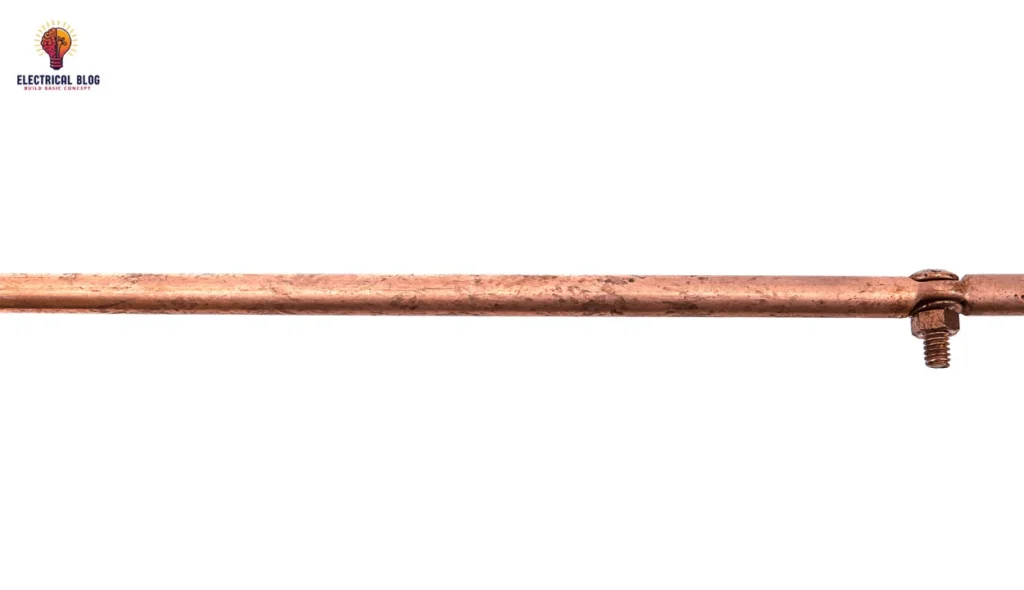
A grounding rod is a metal rod driven deep into the earth to safely disperse excess electricity from an electrical system. It is crucial in electrical grounding to prevent damage from lightning strikes and system malfunctions. By providing a safe path, it helps reduce the risk of electrical hazards during storms and faults. The grounding wire connects it to the service panel, ensuring effective operation.
This device is also used for mobile objects like power generators and vehicles to manage static discharge voltages. A specific term for such rods is an earthing spike, designed for temporary setups. According to the grounding overview, these rods help maintain safety by handling sudden surges of energy.
Read more: Types of Underground Cables
Materials for Ground Rods
Selecting the right materials for a ground rod is crucial for safety and durability.
Copper
Copper is the most commonly used option, often created by coating a steel core to form copper-clad ground rods. These offer excellent reliability and a 40-year lifespan, making them an ideal choice for most environments.
Stainless steel
Stainless steel rods, while expensive, are corrosion-resistant and better suited for areas with high salt content.
Galvanized steel
Galvanized steel is a more economical alternative, produced by applying a protective zinc coating over a steel base to guard against rust. However, factors like salt exposure can erode the zinc layer, reducing its service life.
In such cases, the estimated life drops to 15 years, much shorter than the copper options. These variations represent different needs and conditions, and it is wise to evaluate which material fits best. In my experience, selecting wisely can prevent early replacement and ensure optimal performance over time.
Read more: underground cables

Grounding Resistance
Ground resistance plays a key role in how well a grounding system performs. Factors like length, diameter, and number of ground electrodes affect the system’s performance. As per NEC 250.56, the resistance should be less than 25 ohms. For sensitive applications like ICU units in hospitals, the maximum resistance allowed is 50 ohms (or 50 Ω).
If the impedance goes beyond the recommended value, adding an additional ground rod or supplementary ground rods can help. You may also increase the diameter or increase the number of rods. Standards such as NFPA standards, IEEE 80-2013, and clause 14.5 (a) to clause 14.5 (d) guide how to reduce resistance. In telecommunications applications, bonding and grounding must follow IEEE and IEC guidelines.
The IEC/BS EN 62561-2:2012 recommends 5 – 10 ohms as a good range. If there is higher resistance, soil treatment with salt or charcoal in the earth pit helps improve conductivity. The ground system design must ensure these values are met for effective operation. I have seen many field cases where such small tweaks greatly enhance system stability and safety.
Read more: electric pole
Ground rod in a grounding system
Ground rods are placed at a specific depth below the Earth’s surface, based on local electrical codes and requirements. Their connection to the electrical system is made using conductors and grounding clamps. Proper grounding helps ensure safety and the effective operation of electrical and electronic equipment. It also helps prevent electrical hazards and system disturbances in daily operations.
Protection in Electrical Systems
In electrical wiring, ground rods are driven into the earth to build a strong grounding system. They connect to the grounding conductor in an electrical circuit, linking the rod to the ground terminal. This setup helps dissipate electrical faults, static electricity, and lightning strikes, reducing electrical shock hazards and equipment damage.
Lightning Protection
In lightning protection systems, ground rods work with lightning rods and conductors to provide a safe path for strikes. These parts are connected to dissipate energy into the ground, reducing the risk of fire or structural damage. This extra layer of protection makes a huge difference during storms.
Telecommunications
Telecommunications systems also depend on ground rods to maintain a common ground reference across devices. This protects sensitive equipment from voltage surges and electromagnetic interference. Having a solid grounding setup is key to keeping signals stable and equipment safe.
Industrial and Scientific Applications
In industrial settings and scientific laboratories, grounding systems play a critical role in safety and proper operation. They protect sensitive electronics and help manage volatile materials in controlled environments. From personal experience, grounding has saved costly equipment from failure more than once.
Types of Grounding Rods
Solid copper ground rods
Solid copper ground rods are well known for their strong electrical conductivity and excellent corrosion resistance. They ensure electrical safety by maintaining a solid connection to the earth, aiding fault current dissipation. Their life expectancy typically ranges from 20 to 40 years, making them a reliable part of grounding systems.
Copper-clad galvanized steel ground rods
Copper-clad galvanized steel ground rods combine galvanized steel with a thin copper cladding, offering a cost-effective alternative to solid copper rods. They provide good conductivity and solid performance in most grounding systems. The life expectancy of these rods is around 10 to 15 years, which is suitable for general use.
Copper-coated galvanized steel rods
Copper-coated galvanized steel rods are engineered for durability and consistent performance in various grounding applications. The copper coating ensures efficient conductivity, helping maintain stable operations. These copper-coated galvanized steel rods have a life expectancy of up to 40 years under proper conditions.
Copper-bonded ground rods
Copper-bonded ground rods come with a thick layer of copper bonded to a strong steel core, combining strength and electrical conductivity. This design supports long-term use in advanced grounding systems. Their life expectancy is generally more than 40 years, which is ideal for high-performance needs.
Galvanized steel ground rods
Galvanized steel ground rods are a cost-effective option, commonly used in electrical applications and industrial applications. Though less conductive than copper-based alternatives, they still provide reliable ground connections in many setups. Their life expectancy usually falls between 10 and 15 years.
Stainless steel ground rods
Stainless steel ground rods are chosen for harsh environments due to their excellent corrosion resistance and durability. They offer low maintenance, long-lasting performance, and strong grounding solutions in special applications. These rods can last up to 50 years, making them highly dependable.

How to Install a Ground Rod
Materials Required
The ground rod is the main item in the grounding system. It should be of proper size and inserted straight into the hole using a hammer or sledgehammer.
A shovel or post-hole digger is used for hole excavation. The hole diameter should be around 120 to 150 mm, and the depth must be about 2.4 m, depending on the rod.
Earth-enhancing compound is mixed with water to improve ground resistance. This slurry is poured into the hole and helps to achieve better electrical conductivity.
A grounding wire is connected to the top of the rod and extended toward the electrical panel or alternate grounding point. Packaging from the rod must be removed, and the pointed end should go downward.
Use a grounding clamp to make a secure connection between the grounding wire and the rod. This ensures a safe and efficient energy flow according to installation standards.
Install an inspection chamber or ground pit over the rod to protect it from environmental elements and allow for easy inspections and future maintenance.
Installation Process
Location selection is the first step. Make sure the area is clear of underground utility lines to avoid damage during installation. The place should follow proper electrical system design for safe grounding and future connection use.
Begin excavation using a shovel or digger. The hole diameter should be around 120 to 150 mm, and the depth should be at least 2.4 m for proper placement. Remove any excavated soil from the area to make space for the rod.
Check soil resistivity before installing the rod. If there is higher resistivity, apply suitable soil treatments or go for deeper penetration using additional rods as required by site conditions.
Proceed with rod insertion. Insert the rod straight into the hole using a hammer or sledgehammer. Make sure the pointed end goes downward and that all packaging is removed from the rod.
Attach the grounding wire to the top of the rod and extend it to the electrical panel or an alternative grounding point. Use a grounding clamp to ensure a firm connection and smooth current flow.
Prepare the earth-enhancing compound as per the manufacturer’s instructions by mixing it with water. Pour the slurry filling into the hole to boost ground resistance performance. Let it cure for 1–2 days before final testing.
Complete the process by installing a ground pit or an inspection chamber. It offers protection against environmental elements and supports future maintenance and periodic inspections.
Ground Rod Installation Requirements
Ground Rod Sizing
The ground rod must be installed vertically and driven deep into the soil, at least eight feet (2.45 m) below the ground surface. This standard length is ideal for residential use, but in commercial applications or industrial applications, longer rods may be required due to high soil resistivity or dry soil. Moist soil is preferred because it provides lower resistance and better contact with the rod for effective grounding.
The diameter of a ground rod also matters. Common sizes range from 1/2 inch to 3/4 inch (15 cm to 23 cm), as per grounding rod sizing regulations. Larger diameters offer lower resistance to earth, but they are often expensive, difficult to drive, and may not be necessary for standard setups. Always consider extending rod length before increasing size for better performance.
Other Considerations
Soil resistivity plays a big role in the effectiveness of your ground rod. In very dry soils or rocky soils, reaching the required 8-foot depth can be challenging. In such cases, alternative methods like horizontal installation or multiple rods may be better options.
There are no exact rules for placing the rod, but always maintain at least two feet’ distance from any building structure. Also, install the ground rod near the home’s electrical panel for easier access and better connection to the electrical grounding system.
Ensure the location is accessible and has sufficient space for easy installation. A good selection of the site supports smoother installation and helps prevent disruptions during or after installation.
Use the right tools like a hammer, driving rod, and avoid using a digging tool that can cause damage. Make sure the rod is properly driven into the soil and connected securely to a grounding conductor made of copper or galvanized steel.
When using more than one rod, follow NEC guidelines and keep them spaced at least 6 feet apart. This ensures adequate grounding, especially in areas with high soil resistivity or unsuitable soil types, as often discussed in comparisons like ground plates vs. rods.
Conclusion
Installing a ground rod correctly is essential for ensuring a safe and reliable electrical grounding system. Choosing the right materials is key. You also need to know about grounding resistance. Next, think about soil resistivity, placement, and the size of the ground rod. Each step is vital for a successful installation. Using the right tools and following NEC standards can boost ground resistance. Also, applying earth-enhancing compounds when needed helps improve performance. A good grounding setup is important for homes, businesses, and industries. It protects your systems and boosts safety. Plus, it helps ensure long-lasting durability with little upkeep needed.


