Introduction
Working with electrical systems requires precise tools, and the megger is one such instrument designed to measure insulation resistance. Unlike a standard ohmmeter, which handles low values, a megohmmeter applies high voltage to check for faults in cables, transformers, and other devices. It is especially useful in detecting breakdowns across a broad range, often exceeding 1,000 megohms.
Since the 1920s, engineers have relied on the megger to test various applications, ensuring safety and efficiency in power systems. Whether inspecting multimeters or diagnosing faults in industrial transformers, this tool is indispensable for maintaining stability. With its ability to handle mega resistance levels, it offers a higher standard of accuracy, making it a key asset in electrical diagnostics.
What is a megger?
A Megger is essential equipment for detecting problems in electrical systems by checking insulation and resistance. It applies high voltage to a circuit, allowing current to flow and reveal potential damage or degradation. By conducting this test, professionals can accurately measure weak points and identify potential failures before they become serious.
What is a megger meter?
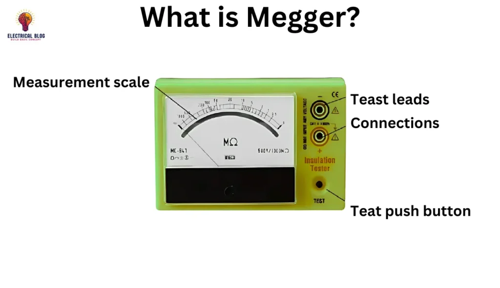
A megger is a specialized tester designed to detect faults in electrical systems by measuring resistance. Unlike a standard ohmmeter, it applies high voltage to check for insulation issues. With an operational range of 50 to 100 volts, it ensures accurate readings across a wide range. Professionals prefer it over a multimeter, as a 9V battery cannot generate enough current to measure 1,000,000 ohms of resistance.
The megger meter consists of a DC generator and a series-type resistance-measuring mechanism. The battery or larger power source enhances sensitivity, allowing precise measurements. Using electromagnetic induction, the device increases the amps, ensuring a reliable test for insulation degradation. Unlike traditional methods, it prevents errors caused by a weak coil or an insufficient deflection response.
With the formula I = V/R, a megger provides highly accurate results by producing an adequate current flow. This instrument outperforms standard tools, as its increasing power eliminates reading discrepancies. Whether for industrial or field applications, this portable device remains essential for ensuring electrical safety.
Megger diagram
Working Principle of Megger
The principle of a megger is based on electromagnetic attraction, where a generator produces a steady high voltage to check insulation resistance. A hand-driven crank rotates the armature, ensuring a constant speed for accurate measurement. The system includes a centrifugal clutch to maintain voltage stability, preventing sudden variations. This allows a steady current to flow through the circuit while testing.
The mechanism consists of coils A and B, acting as a voltmeter and ammeter, forming one instrument. The terminal X connects to the equipment, while terminal Y is grounded. When the handle is turned, voltage is generated, and if there is no leakage, the needle moves towards infinity. If leakage exists, the deflecting force of coil B interacts with coil A, shifting the pointer to indicate the insulation value.
For effective testing, voltage is applied across R1, and current passes through the system to detect faults. Megger meters are available in different voltage ranges such as 500V, 1000V, 2500V, and 5000V. These devices are either motor-operated or power-operated, allowing flexibility in various applications. The slip mechanism ensures that a constant current is applied without fluctuations in readings.
The moving element inside the megger ensures precise readings by balancing the forces between the deflecting and steady torques. The insulated components and body structure protect the instrument from external interference. With a strong lever and durable construction, they provide reliable testing for industrial and electrical applications, making them essential tools in insulation testing.
Construction of Megger
It is an essential instrument that combines a series-type ohmmeter and a DC generator to measure resistance. The device consists of two coils, V1 and V2, positioned at a right angle for accurate readings. A hand-driven system or battery powers the generator to produce the necessary voltage. The circuit is designed to handle low and high resistance values efficiently.
The coils work together with permanent magnets to create a magnetic field, allowing smooth movement of the pointer. The pressure and control coils are connected in parallel to regulate the current flow. As the test begins, the current is drawn through the circuit, interacting with the deflecting coil. The force generated helps the pointer pass through the scale and indicate the measured value.
On the front of the meter, the scale ranges from zero to infinity, helping users read precise insulation values. It is designed to protect itself from damage by considering external factors like electrical interference. The tested object influences the opposite torque, ensuring a reliable test. With positioned components and durable construction, it remains a critical tool for insulation testing.
Types of Meggers
There are two types of megger used for insulation testing: digital and electrical. A digital meter operates with a battery as its source, providing a stable supply for accurate readings. On the other hand, an electrical megger relies on a hand-driven DC generator, producing voltage manually for testing insulation resistance.
Insulation Resistance Test for Megger
To check insulation, it is used as a tool for accurate measurement. One terminal is connected to the positive side of the wire, while the other goes to the ground or earth. When the crank is rotated, an electromagnetic field (EMF) is generated, causing the pointer to deflect and indicate the resistance value. If the reading is infinite, the insulation is intact; if it is zero, it is incapable of withstanding high voltage.
The TEST begins by attaching probes to the conducting part of the wire and the outer insulation. If the wire can handle 6 Amps, applying the same input does no harm, but exceeding it makes the wire ineffective. The instrument displays the operational condition, with readings classified into different levels. Abnormal insulation falls between 5-10 megaohms, while 10-50 megaohms is considered good.
For strong insulation, values between 50 and 100 megaohms are very good, and above 100 megaohms is excellent. The manual or digital megger applies 1,000 volts or more to ensure reliability. The system maintains a minimum insulation value per volt for safety. If the wire fails, its insulation cannot withstand the currents, leading to electrical faults.
With a line properly set up, an operational test confirms whether insulation meets required standards. The handle on a manual megger allows steady control, while digital models automate the process. A properly functioning ensures safe electrical operation by preventing power loss and system failure. This testing method is essential in verifying insulation strength across various applications.

Uses of Megger
It is used to measure the insulation resistance of wires, ensuring safety in electrical circuits.
It helps evaluate the performance of components and systems by detecting faults in their connections.
The device is essential for testing the battery, relay, and ground integrity to prevent power failures.
During equipment setup, it assists in installing motor windings and verifying proper earth bonding.
A Megger tester is widely used in industrial and domestic applications for various tests and maintenance checks.
Advantages of Megger
The operation is simple, making it easy to use for checking electrical insulation.
It does not require an external power source like a battery or plug, making it independent.
A DC generator with a permanent magnet ensures reliable insulation testing without extra wiring.
The cost of a megger is less than that of other insulation-testing devices.
It helps identify physical damage and leakages, preventing electrical shocks and hazards.
Disadvantages of Megger
The time required for measurement is greater, making the testing process slower than that of other modern methods.
The accuracy of this instrument is not high, which may affect precise insulation resistance readings.
Conclusion
It is an essential instrument used to measure insulation resistance in electrical systems, ensuring safety and reliability. It operates using a DC generator, battery, or hand-driven mechanism to produce high voltage for testing. With applications in wiring, grounding, battery testing, and relay inspections, it is widely used in industrial and domestic environments.
Despite its advantages, such as being cost-effective, simple to operate, and requiring no external power source, iy also has limitations. The time required for measurement is greater, and its accuracy is not high, which may impact precision. However, when used correctly, it remains a valuable tool for ensuring electrical safety and preventing leakages, shocks, and damage in circuits.
FAQs About Megger
How to Use a Megger?
To use a megger, connect one terminal to the insulation and the other to the ground. Rotate the crank (for manual models) or press the TEST button (for digital models) to apply high voltage. The pointer will move on the scale to indicate the resistance value. A higher reading means good insulation, while a low or zero reading suggests insulation failure.
How to megger a 3-phase motor?
First, disconnect the motor from the power supply and remove any connections between the windings. Attach the megger leads—one to the ground and the other to one of the motor windings. Apply the test voltage and observe the reading. Repeat the process for each phase. A healthy motor winding should have high insulation resistance.
How to megger a motor?
To megger a motor, disconnect it from the circuit and ensure it is not energized. Connect one megger probe to the motor frame (ground) and the other to the winding terminal. Apply the megger test voltage, and the reading should indicate the insulation condition. If the resistance is low, the motor may have insulation issues.
How to megger a transformer?
Before testing, ensure the transformer is disconnected from the power source. Connect one megger lead to the core or ground and the other to the HV winding. Perform the insulation test by applying the megger voltage, typically 500V to 5,000V, depending on the transformer’s rating. The insulation resistance should be within the acceptable range for a properly functioning transformer.
What is the power supply to a Megger? The supply to the Megger is?
It can be powered by a DC generator (hand-driven), a battery, or an external power source, depending on the type. Manual meggers use a hand crank to generate voltage, while digital meggers operate on batteries or an AC/DC power supply. The typical megger test voltage ranges from 500V to 5,000V, depending on the insulation test requirements.