Introduction
A varactor diode is a voltage-controlled semiconductor device that acts as a variable capacitor in electronic circuits. It is designed to operate in reverse bias, where its capacitance changes with applied voltage. These diodes are widely used in tuning circuits, frequency synthesizers, and phase-locked loops. Their small size, economical nature, and low noise make them essential in RF and wireless communication systems. However, they have some downsides. These include non-linear behavior, temperature sensitivity, and distortion in certain uses.
What is a varactor diode?
A varactor diode is a specialized semiconductor device that is utilized for its variable capacitance rather than conduction. Unlike standard diodes, it is designed to work in a reverse-biased mode, making it highly valuable in frequency tuning circuits. Its capacitance changes with applied voltage, allowing precise frequency adjustments in communication systems. The PN junction of this diode behaves like a capacitor, making it essential for various electronic applications. This key feature is widely exploited in radio frequency and microwave technology.
The first commercial varicap was developed by Pacific Semiconductor, a subsidiary of Ramo Wooldridge Corporation, and later became a successor product of TRW. The term “Varicap” comes from the fusion of “variable” and “capacitor,” emphasizing its key functionality. It was officially obtained and trademarked in October 1967, marking an important historical milestone in semiconductor technology. The nonlinear characteristics of this device make it ideal for applications requiring precise control over signal frequencies. Due to its unique reactance property, the varactor diode continues to be a critical component in modern electronics. You can also read vacuum diode.
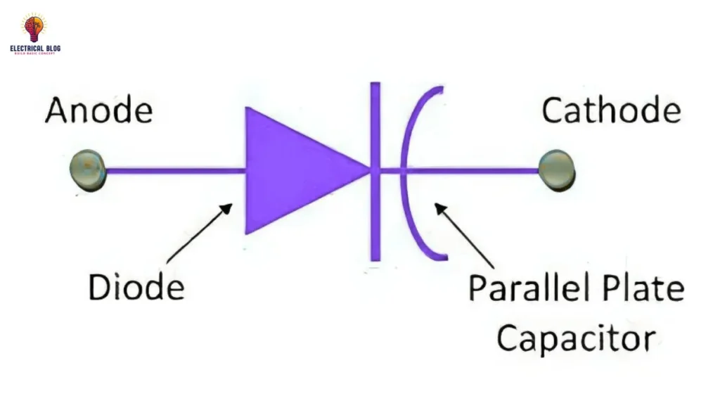
Symbol of Varactor Diode
The symbol of a varactor diode is similar to that of a PN-junction diode, with a capacitor representation. It has two terminals, the anode and cathode, which indicate its electrical connections. One end of the symbol has a diode, while the other shows two parallel lines representing the conductive plates of a capacitor. The gap between these plates signifies the dielectric, highlighting its charge storage property.

varactor diode diagram
Formula of Varactor Diode
The relationship between capacitance and the depletion layer in a varactor diode shows that transition capacitance (CT) is inversely proportional to width. It follows the formula:
CT = ɛA/W
where ɛ is the dielectric constant, A is the capacitor plate area, and W is the depletion width. This can be further simplified as:
CT = CK/(Vb – V)^m
where Vb is the barrier voltage, V is the applied voltage, and m depends on the material.
The quality factor of the varactor diode is defined by:
Q = F/f
where F is the maximum operating frequency, and f is the actual working frequency. A large capacitance magnitude is achieved when the reverse voltage is low, keeping the depletion width minimal.
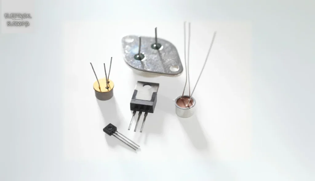
Construction of Varactor Diode
The construction of a varactor diode is based on a p-n junction, which is created through a doping technique. It consists of a p-type region with positively charged holes and an n-type region containing negatively charged electrons. The depletion region forms at the boundary, and its width changes with applied voltage. When forward bias is used, this region becomes narrow, allowing current flow, while in reverse bias, it becomes wide, blocking most current.
The integral part of this semiconductor is made from materials like silicon or gallium arsenide (GaAs), with silicon being commonly used due to its lower capacitance range. Metal contacts are added to provide proper electrical connections for an external power source. These connections enable the variable capacitance property, making the varactor diode essential in tuning circuits. The wafer structure and impurities in the material ensure the diode performs efficiently under different biasing conditions.
Working of Varactor Diode
A varactor diode works by controlling its capacitance through reverse biasing, which changes the depletion region width. It consists of a p-n junction made from semiconductor material, where the n-type region has electrons and the p-type region has holes as the majority carriers. When connected in reverse bias, the depletion region increases, and the capacitance decreases, allowing it to store electrical energy like a capacitor. If forward bias is applied, the depletion region becomes small, causing charge to flow, which is undesirable for its operation. This is why a varactor diode always operates in reverse bias to maintain controlled storage of charge.
The PN-junction acts as a dielectric, preventing current from flowing, while the permittivity and area of the junction determine its total capacitance. A larger width of the depletion region means fewer ions and lower capacitance, while a smaller width increases the capacitance for higher storage. The equation governing this behavior shows that the total charge stored depends on the applied voltage. The positive and negative ions in the region help regulate its electrical properties, ensuring precise frequency tuning. The ability to move and control this charge makes varactor diodes useful in high-frequency circuits.
Varactor Diode Characteristics
A varactor diode is a voltage-controlled device that is widely used in tuning circuits. It operates in reverse bias conditions, meaning there is no conduction of current. Often called a varicap, this type of diode functions as a variable capacitor based on the applied voltage.
Variable Capacitance Characteristics
A varactor diode is specially manufactured to enable controlled capacitance variation in electronic circuits. Unlike normal diodes, it is optimized to provide high-range changes in capacitance when voltage is applied. The junction properties of the diode play a key role in its performance. This type of diode is categorized based on its ability to deliver the required capacitance shifts, making it the preferred choice for tuning applications.
Applications of Varactor Diodes
Varactor diodes are widely used in the RF industry for applications requiring voltage-controlled frequency adjustments. They are essential in oscillators and VCOs, where precise tuning is needed. Their ability to adjust capacitance by applying different voltages makes them useful in many electronic circuits.
In receivers, varactor diodes help in tracking and filtering signals to improve reception quality. They are used in filters within the front end of communication devices to enhance performance. Their role in voltage control ensures seamless frequency adjustments in radios and wireless systems.
These diodes play a major role in phase-locked loop circuits, allowing stable frequency generation. Their capability to vary frequencies makes them ideal for precise signal control. They are also found in different sectors where frequency stability is critical.
The method of using varactor diodes in tuning applications is common in the design arena. Their ability to respond to control voltages ensures flexibility in frequency selection. With their presence in modern radios, they remain essential for stable signal processing.
Advantages of Varactor Diodes
Varactor diodes act as voltage-controlled capacitors, making them useful for tuning circuits in radio and communication systems.
It is economically beneficial and affordable, allowing for use at different levels where precise frequency control is needed.
Phase-locked loops (PLLs) and frequency-locked systems use varactor diodes to generate and control accurate frequencies.
They are commonly used in multipliers, dividers, and phase shifters to divide or adjust high-precision signals.
Their small size, low noise, and efficient properties make them ideal for electronic devices such as frequency synthesizer systems.
Disadvantages of Varactor Diodes
Varactor diodes are mode-specific and designed to operate only in reverse bias, making them not useful for forward-bias applications.
Their non-linear behavior creates an unstable capacitance-voltage relationship, which can cause distortion in sensitive appliances.
These diodes are temperature-sensitive, meaning their capacitance is affected by temperature variations, leading to performance issues.
Conclusion
The varactor diode is a PN junction device primarily used in reverse bias to achieve variable capacitance. Its non-linear traits form a special link between voltage and capacitance. This makes it great for various uses. It is affordable, but it has limits. It is sensitive to temperature and works in specific modes. The curve of its performance varies with variations in external conditions, affecting its work in some cases.