Introduction
From my years working with industrial power systems, I’ve seen how the right connection can make a huge difference in a three-phase transformer setup. Whether it’s a Delta-Delta, Wye-Wye, Delta-Wye, or Wye-Delta configuration, each one plays a critical role in the overall transformer’s performance. These configurations are defined by how primary and secondary windings are arranged, which directly affects voltages, performance, and suitability in real-world applications.
In many installations, I’ve found that choosing the right internal connection impacts everything from load handling to fault management in the power system. While single-phase transformers are useful, combining them correctly into a three-phase transformer brings better characteristics for industrial applications. Whether it’s a star-star or delta-wye setup, every connection must be evaluated based on operational performance and system needs. In this article, we will cover three-phase transformer connections.
What are the three-phase transformer connections?
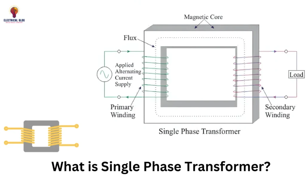
In my practical experience, a three-phase transformer is made by linking three single-phase transformers that are electrically tied internally. These connections between primary and secondary windings form a complete unit designed to handle different voltages. The setup can be arranged in star, delta, wye, or a combination of these configurations.
Each connection affects the transformation ratio, phase shift, and grounding provision, depending on system factors. The right design must be suitable for specific applications, especially when dealing with primary and secondary voltages. These technical choices play a major role in achieving efficiency and reliability in real-world installations. You can also read transformer parts.

Types of Three-Phase Transformer Connections
Delta – Delta (Δ – Δ) Connection
Star – Star (Y – Y) Connection
Delta – Star (Δ – Y) Connection
Star – Delta (Y – Δ) Connection
Open Delta or V-V Connection
Scott Connection
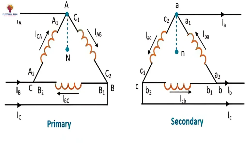
Delta – Delta (Δ – Δ) Connection
In real-world electrical systems, the delta-delta configuration is highly effective for handling heavy loads in industrial plants. Here, both primary and secondary windings are delta connected, forming a delta-delta transformer that ensures stable three-phase power. The voltage ratio matches the turns ratio, and under balanced conditions, the line current becomes √3 times the phase current.
Key Characteristics:
Phase voltage equals line voltage, ensuring better voltage handling.
Triple harmonics are canceled due to a closed loop of third-harmonic currents.
Suitable for systems with a lagging power factor (cosφ) and a stable output voltage waveform.
Works efficiently under balanced and unbalanced loads without affecting polarity or current ratios.
Advantages:
Ensures fault tolerance; in case of malfunction, three-phase power is still maintained via open delta (V connection).
No need for a neutral point at primary levels or secondary levels when working with low voltages or moderate voltages.
Operates well even when the magnetizing current is ignored in figure-based load analysis.
Star – Star (Y – Y) Connection
In many of my transformer installations, the Y-Y setup is a straightforward method where both primary and secondary windings are star-connected. It’s commonly used in three-phase transformer systems for balanced loads, especially in smaller load conditions. However, certain major issues often arise in practical usage that must be addressed for smooth performance.
Key Characteristics:
Line voltage is √3 times the phase voltage, making it efficient for energy transmission.
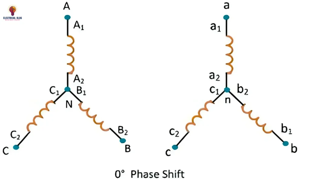
There is no phase shift between the primary side and the secondary side under ideal conditions.
Works well when loads are balanced, as shown in the phasor diagram.
Key Issues:
Lack of a proper neutral connection causes voltage imbalances during unbalanced or uneven loads.
Third harmonics and magnetizing current can distort voltage across phases and affect magnetic flow.
An unstable neutral point can lead to distorted voltages in the Y-Y setup.
These issues can be fixed by solidly grounding the neutral or using extra windings, like tertiary windings.
Delta – Star (Δ – Y) Connection
In practical distribution work, I’ve often used the Delta-Star (Δ – Y) connection where the primary winding is delta connected and the secondary is star connected. This setup is widely used in distribution systems for step-down of voltage. As shown in the figure and phasor diagram, a 30° phase shift occurs between the primary and secondary sides.
Van, VBN, Vcn, and VAN illustrate this shift, with secondary phase voltage leading the primary phase voltage. This setup can also be adjusted as a +30º connection or -30º connection based on system needs. These adjustments help balance the voltage in the secondary system and the primary system.
Key Characteristics:
The ratio of line voltage to phase voltage is 1/√3 (VLS = √3 VPS).
Supports single-phase loads on the secondary side.
Ideal for applications requiring reliable voltage transformation in distribution systems.
Star – Delta (Y – Δ) Connection
In my experience with power transmission systems, the Star-Delta (Y-Δ) connection is an efficient choice for stepping up voltage. Here, the primary winding is star-connected and the secondary is delta-connected, creating a smooth energy transfer across lines. The phasor diagram clearly shows a 30° phase shift in the Y-Δ transformer connection, which is crucial in many setups. In this Y-Δ configuration, each phase in the star-connected side leads the next by 30 degrees. The voltage ratio between line voltage and phase voltages is generally represented by √3, ensuring reliable performance.
What I’ve found particularly effective is how the delta winding handles unbalanced loads without needing a neutral wire. The third harmonic currents circulate through a closed path across winding phases, maintaining system balance. You may also come across a +30 degree star-delta transformer connection, or its reverse, the -30 degree star-delta connection, where voltages lag instead of lead. This flexibility allows adjustment depending on system requirements and load conditions. Such a star-delta configuration proves ideal for large-scale transmission systems where currents, voltage, and winding stability are critical.
Key Characteristics:
Voltage ratio in Y-Δ configuration is √3 between line voltage and phase voltages.
Provides an efficient step-up in transmission systems.
Handles unbalanced loads effectively using delta windings.
Open Delta or V-V Connection
In practical power systems, an open delta or V-V connection is used when one transformer fails or is removed for transformer maintenance. In this case, two single-phase transformers form a two-transformer bank instead of a full three-transformer bank. The system still supplies three-phase power, but with a reduced capacity of 58% of the original three-transformer bank rating. The primary windings are set in a delta configuration with one leg open, creating an open delta connection. This setup ensures continuous operation even during maintenance.
According to Kirchhoff’s voltage law, Vab, Vbc, and Vca are the phase voltages induced across the secondary winding, with one path vectorially generated by adding secondary voltages. In this delta transformer connection, the third leg remains incomplete, causing the phase terminals a and c to be open. This leads to changes in circulating current and uneven current loads in the remaining phase winding. Each transformer carries more current, and full line current is distributed unevenly. This rise causes excessive currents and can result in overload and possible breakdown if not properly managed.
As observed in the phasor diagram, Vp at the primary side still drives the system, but the increased current creates stress. To avoid transformer damage, you must reduce load by a factor of √3, preventing thermal overload and extending rated capacity. If not handled, each unit reaches 73.2% of its rated load, risking failure. In my experience, using this connection in places where a one-phase outage is expected has helped maintain operations reliably. It’s a clever solution for critical applications needing backup during faults or servicing.
Key Characteristics:
Total capacity of the system becomes 57.7% in an open delta arrangement.
Carries three-phase power with just two transformers.
Effective during transformer maintenance or a one-phase outage.
Scott Connection
The Scott connection is a smart solution I’ve used often to connect two transformers for converting three-phase power into two-phase voltages. One is the main transformer with a center tap, and the other is the auxiliary transformer with an 86.6% tap. Both are electrically tied but remain magnetically isolated, keeping the transformer cores free from mutual interference. This design allows for a smooth voltage transformation using limited components.
For three-phase to single-phase conversion, three-phase supply voltages are applied to the primary winding of the main transformer. The auxiliary transformer primary is phase-shifted by 30 degrees and works in parallel to support the conversion. In single-phase to three-phase conversion, the source voltage is applied to the combined secondaries for a balanced three-phase output. The system ensures stability on the secondary side, delivering clean line-to-line voltage to the load.
One of the best things about this method is that it enables 1-φ to 3-φ and 3-φ to 1-φ conversion easily. I’ve used it in places where only single-phase power was available, yet we needed three-phase power for running equipment. It prevents overloading and keeps the system reliable under different load conditions. The Scott connection is not only efficient but also a cost-effective solution.
With proper phase shift and control over third phase voltage, it becomes ideal for special applications like two-phase systems. It provides excellent performance without complex wiring or additional equipment. Whether for industry or grid setups, this transformer configuration is a practical choice for consistent output and reliability.
Factors Affecting the Choice of Connection
In my experience with transformer design and installation, choosing the right connection type depends on several real-world conditions. Each setup has its strengths, but you must evaluate the system requirements carefully before deciding. Below are key points I always consider during system planning:
Primary voltage levels and secondary voltage levels must match the load and network design.
The loading condition — whether balanced or unbalanced — affects system performance and stability.
Fault tolerance requirements are important in critical systems that must keep running during faults.
Always check the grounding requirement, especially in sensitive or safety-critical environments.
Harmonic content in the system can impact transformer life and should be minimized.
Space constraints and cost constraints also influence whether compact or economical options are preferred.
The intended power transfer direction, such as step-up or step-down, will determine the appropriate connection configuration.
Conclusion
Each connection type—Delta-Delta, Star-Star, Delta-Star, Star-Delta, Open Delta, or Scott Connection—serves a specific purpose and offers unique benefits and applications. The choice depends on several factors: primary voltage levels, secondary voltage levels, loading conditions, fault tolerance needs, grounding requirements, and harmonic content in the system.
Engineers can choose the best configuration by considering practical insights. They need to think about space limits, cost, and whether the power transfer is a step up or a step down. When done carefully, these connections boost fault tolerance. They also allow flexible voltage changes and ensure steady power delivery, even in tough situations.