Introduction
A single-phase transformer is a key component in electric systems, designed to transfer energy between circuits by adjusting voltage levels. It can step up or step down AC voltage, making it useful for a wide range of applications. The construction of these transformers is simple yet efficient, ensuring reliability across various uses. They are classified based on function, whether for residential, industrial, or commercial needs. While they offer many advantages, such as efficiency and cost-effectiveness, they also have disadvantages, like limited capacity for large power demands. Understanding their definition and role in electrical systems helps in making informed choices.
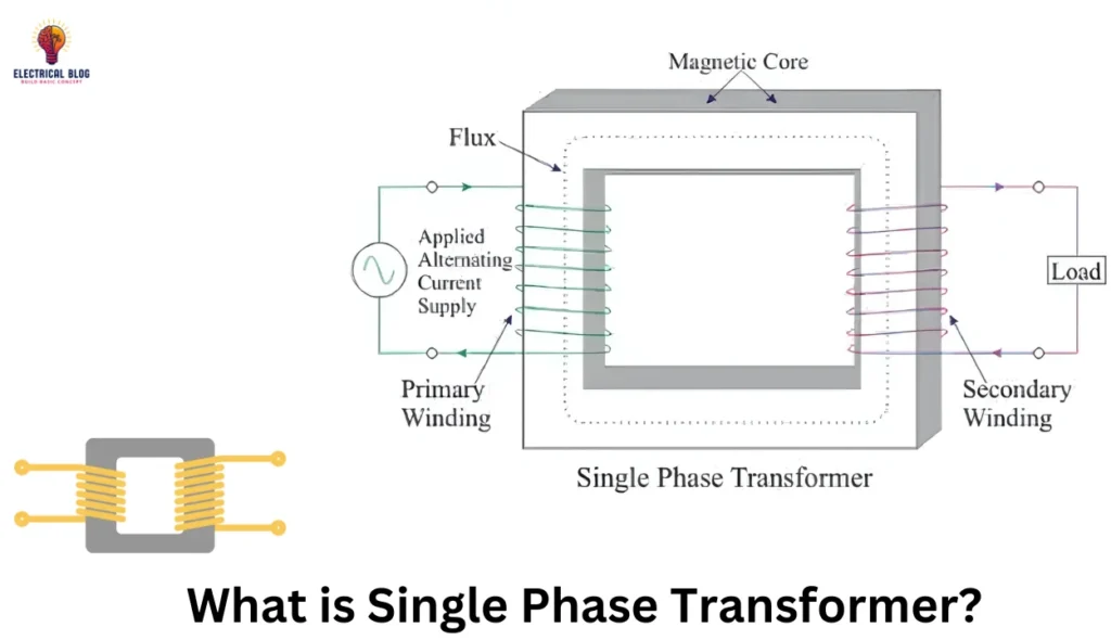
What is a single-phase transformer?
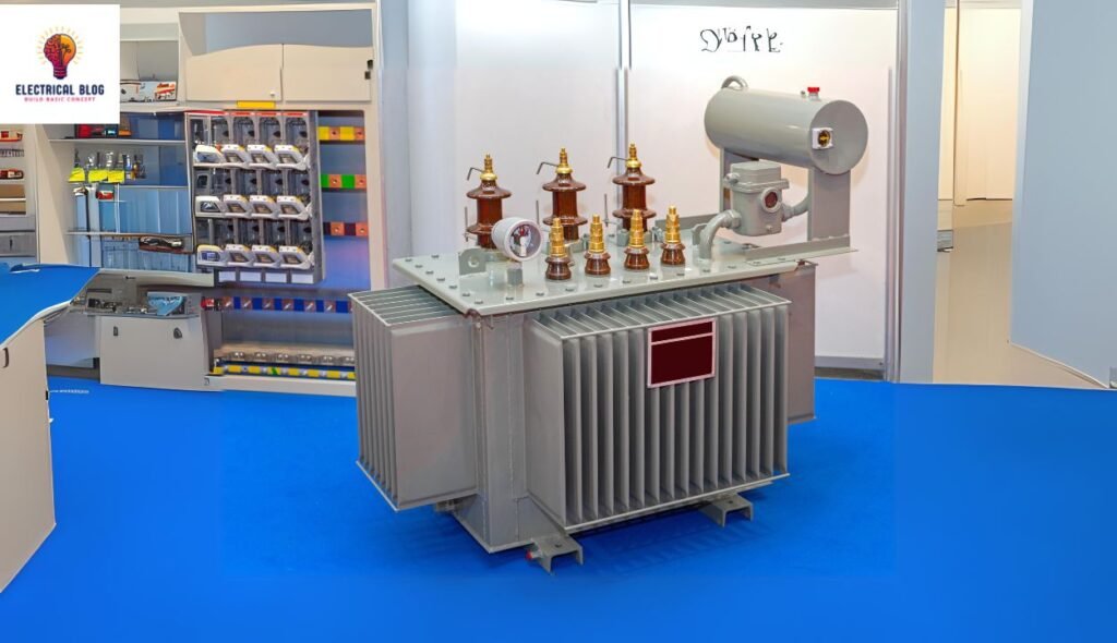
A single-phase transformer operates using alternating current, as direct current cannot create an electromagnetic field. It consists of two parts—the magnetic transformer with a magnetic iron core and the electrical side, which includes the copper transformer. The construction of these transformers ensures minimal friction and mechanical wear since they have no moving parts.
When current flows through the primary winding, it generates a changing electromagnetic field that spreads through the windings. Due to mutual induction, a voltage is induced in the secondary winding, allowing energy transfer. The frequency of the voltage in the secondary winding remains the same as in the primary winding, as explained by Faraday’s Law.
The overview of these transformers highlights their efficient performance with minimal energy loss. Engineers rely on calculations to determine the exact value of voltage transformation for different power needs. A well-designed article can further explain the construction and working principles of single-phase transformers in various applications.
Single-phase transformer diagram

Faraday’s Principle of Electromagnetic Induction
Faraday’s Law explains how a magnetic field can interact with a conductor to produce an electromotive force (EMF). The first law states that whenever a varying magnetic field crosses a circuit, an induced EMF is generated. The second law defines that the rate of change of flux linkages determines the strength of the electromotive force. This principle, known as electromagnetic induction, is essential for transformer operation.
working principle of a single-phase transformer
A single-phase transformer works on the principle of mutual inductance, where an alternating current flows through the primary windings. This causes a build-up of a magnetic field in the core, creating magnetic lines of force. As the current increases, the magnetic flux strengthens, ensuring efficient energy transfer.
The flowing magnetic flux links the secondary winding, inducing a voltage as per Faraday’s Law. The turns ratio between the primary windings and the secondary winding helps determine the value of the generated voltage. Since magnetic flux and current are directly proportional, any increase in input power leads to a rise in output voltage.
This system ensures stable power conversion, making the transformer efficient for various applications. The strength of the magnetic field in the core plays a key role in performance. A well-designed coil structure ensures that energy loss remains minimal while maintaining consistent power delivery.
Structure of a Single-Phase Transformer
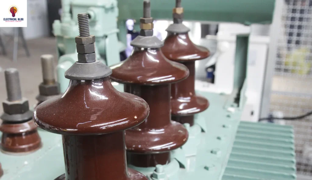
A single-phase transformer is constructed with a magnetic core made of silicon steel to provide a path for the magnetic flux. The primary winding and secondary winding are wrapped around the core-type or shell-type structure. To minimize hysteresis losses and eddy currents, the core is built using thin sheets of laminations.
Each lamination is coated with an insulating coating like enamel to insulate against localized electric current caused by a varying magnetic field. This construction reduces energy loss and improves efficiency. The windings are carefully placed to ensure a smooth induced current flow through the conductor for optimal performance.
Core-Type Transformer
A core-type transformer has two vertical legs called limbs and two horizontal sections known as yokes that guide the magnetic current. The primary windings and secondary windings are placed on each limb, with half on one side to minimize the effect of leakage flux. This design improves efficiency and ensures better performance in power distribution.
Shell-Type Transformer
A shell-type transformer has three limbs in its magnetic circuit, with the middle limb holding the windings. The primary windings and secondary windings are divided into subdivisions, separating the low-voltage and high-voltage sections. The other limbs help complete the flux path, ensuring low reluctance for efficient energy transfer.
Load Test on Single-Phase Transformer
A load test is conducted on a transformer to measure its efficiency and losses at different loads. The primary winding is energized at a fixed frequency, while the secondary load is gradually increased in steps. The primary current, secondary current, and power input are noted, and efficiency is calculated using the ratio of output power to input power.
EMF Equation of a Single-Phase Transformer
The induced EMF in a winding depends on the flux changes according to Faraday’s Law. In an AC supply, the flux density varies in a sinusoidal wave, causing an EMF that lags the flux by 90 degrees. The relationship between the number of turns in the primary winding (N1) and the secondary winding (N2) gives the transformation ratio (K).
Step-by-step EMF equation:
Magnetic flux (φ) is in a sinusoidal form.
ϕ = ϕm sin(wt)
Differentiating flux with respect to time.
dϕ/dt = ϕm w cos(wt)
Induced EMF in the primary winding (E1):
E1 = -N1 dϕ/dt
E1 = -N1 ω φ_m cos(ωt)
Maximum value of induced EMF (E1max):
E1max = N1wϕm
Using angular frequency (ω = 2πf)
E1max = 2πfN1ϕm
RMS value of induced EMF (Erms) using the form factor (1.11).
E1=4.44fN1BmAi
Similarly, for the secondary winding (E2).
E2 = 4.44 fN2BmAi
Turn ratio equation
E2/E1 = N2/N1 = K
Difference between single-phase and three-phase transformers
A single-phase transformer requires two wires, while three-phase transformers require four wires to complete the circuit.
Single-phase transformers carry 230V, whereas three-phase transformers carry 415V, making them suitable for higher power applications.
A single-phase transformer uses a simple network, while a three-phase transformer operates on a complicated network to handle greater loads.
Power failure occurs in a single-phase transformer, but there is no power failure in three-phase transformers due to continuous power distribution.
Three-phase motors experience reduced vibrations as power is distributed uniformly throughout the cycle, ensuring smoother operation.
Single-phase transformers are ideal for home appliances, while three-phase transformers run heavy loads in industrial settings.
Applications of Single-Phase Transformers
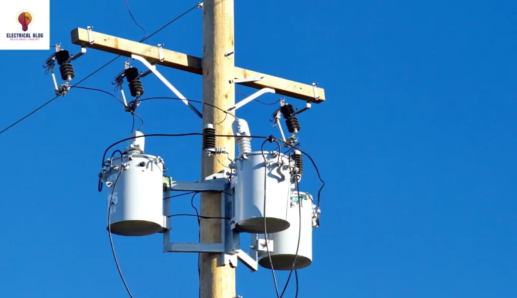
Single-phase transformers are used in localized power distribution to decrease voltage in certain areas where lower power is needed.
They help in the regulation of voltage for television sets, ensuring stable performance and protecting circuits from fluctuations.
Increasing the voltage in home inverters is a key function, allowing for a stable power supply to household appliances.
Commonly used in heating devices and lighting, they ensure a consistent power flow for daily electrical needs.
Ideal for rural areas with low demand for electricity, which makes the energy supply more efficient in remote locations.
Advantages of Single-Phase Transformers
The system is highly reliable, as transformers can be connected in parallel, ensuring service continuity even during maintenance.
It helps reduce the possibility of overloading by balancing the load and preventing damage to electrical components.
The transformer can switch on or off automatically based on demand, making energy usage more efficient.
Disadvantages of Single-Phase Transformers
Single-phase transformers are costly to maintain, making them less economical for large-scale applications.
They require a lot of installation space, which can be a challenge in compact electrical setups.
There is a chance of failure when transformers are connected in parallel, affecting system reliability.
Conclusion
A single-phase transformer is a crucial electrical device used for power distribution, voltage regulation, and energy efficiency. It operates based on Faraday’s Law, utilizing mutual inductance to transfer power between the primary winding and secondary winding. The core-type and shell-type designs influence performance, and the EMF equation helps determine voltage transformation.
Single-phase transformers are reliable and efficient, but they have some downsides. They can be costly to maintain. They also need a lot of space for installation. Plus, if you connect them in parallel, there’s a risk of failure. Their benefits in local power distribution, home appliances, and rural electricity make them vital for many uses. Knowing how they are built, how they work, and their pros and cons helps you choose the right one for your needs.