Introduction
When I was a kid, I had a toy car that ran on a battery, and I always wanted to enjoy playing with it for longer. But I noticed that sometimes the battery drained too fast. Later, I learned that the Power Triangle explains how power is used efficiently in electrical systems, including motors. It shows how Active Power (P) is responsible for actual work, while Reactive Power (Q) supports the magnetic field, and Apparent Power (S) is the total power drawn. Just like managing a battery’s consumption, understanding the Power Triangle helps reduce unnecessary losses and make electrical devices more efficient.
In AC circuits, the Power Triangle plays a crucial role in analyzing the relationship between these three power components. The Power Factor, whether Leading or Lagging, affects how efficiently power is transferred. Engineers use this concept to optimize motors, ensuring they move in the right direction and rotate smoothly. By applying these principles, we can achieve better efficiency in electrical systems, from industrial machines to everyday appliances. Understanding the Application, Advantages, and Disadvantages of the Power Triangle can help solve electrical challenges, and by working through practical cases and solved problems, we gain a depth of knowledge to conclude effective solutions.
What is a Power Triangle?
In AC circuits, the Power Triangle is a right-angled triangle that helps in understanding electrical power relationships. Its hypotenuse represents the apparent power, also called true power (S), while the opposite side shows the reactive power (Q), and the adjacent side corresponds to the active power (P), which does actual work. According to Pythagoras’ theorem, these values follow the equation S² = P² + Q². The angle between S and P determines the Power Factor (cos θ), which affects efficiency. The Power Triangle has two primary types: Leading Power Factor and Lagging Power Factor, which indicate whether the load leads or lags in phase with the supply.
Power Factor
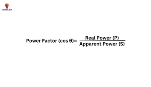
In the Power Triangle, the Power Factor tells how efficiently electrical power is being used. It is the ratio of Active Power (kW) to apparent power (kVA) and is given by cos θ. Since it is the cosine of the angle or phase difference between voltage and current, it is a dimensionless quantity. In simple terms, a higher Power Factor means better energy usage, while a lower one indicates power loss due to the load impedance. It is usually written as kW/kVA, showing how much of the supplied power does actual work.
 Examples of power factor values in common electrical systems
Typical power factor values vary across systems:
Residential loads: 0.85 to 0.9 (due to resistive and reactive loads)
Industrial machinery: 0.7 to 0.8 (often need correction to avoid penalties)
Motor loads without correction: 0.6 to 0.75.
Calculating Each Power Type in AC Circuits
The three main types of power present in AC circuits are apparent power (S), reactive power (Q), and active power (P). These are interconnected in the power triangle and are essential for understanding circuit behavior.
Formulas for Active, Reactive, and Apparent Power
Active Power (P) – Measured in watts (W), active power represents the actual power consumed by the load. Formula:
P = V × I × cos θ
where V is voltage, I is current, and cos θ is the power factor.
Reactive Power (Q) – Measured in Volt-Amps Reactive (VAR), it is the power that oscillates between the source and reactive components, such as inductors and capacitors.
Formula:
Q = V × I × sin θ
Apparent Power (S) – Measured in Volt-Amps (VA), apparent power combines both active and reactive power, representing the total power in the circuit.
Formula:
S = V × I
Alternatively, S can also be calculated as:
S² = P² + Q²
Example Calculations
Suppose an AC circuit has:
Voltage (V) = 230 V
Current (I) = 10 A
Phase angle (θ) = 30°
Active Power (P):
P = 230 × 10 × cos(30°) ≈ 2300 × 0.866 ≈ 1991.8 W
Reactive Power (Q):
Q = 230 × 10 × sin(30°) ≈ 2300 × 0.5 ≈ 1150 VAR
Apparent Power (S):
S = 230 × 10 = 2300 VA
or using the power triangle:
S = sqrt(1991.82 + 11502) ≈ 2300 VA
These calculations clarify the relationships among P, Q, and S, highlighting how each type of power affects overall circuit performance.
Power Factor Improvement
To achieve power factor correction, a capacitor can be installed in parallel with the load, ensuring that the current and voltage are completely in phase. This method is known as a way to get unity power factor without altering the original load conditions. The effect of this adjustment can be understood using the Power Triangle or the Phasor Diagram. By choosing a suitable size of capacitor, the power factor can be improved, which is most useful for systems that rely on inductive loads. Since increasing the power factor reduces wasted energy, it plays a key role in optimizing electrical performance while ensuring efficient power usage.
Power Triangle Diagram

Evolution of Power Triangle
The Power Triangle has evolved as an essential tool in AC circuits, helping engineers analyze and improve power usage. Just like an organism that undergoes adaptation, the triangle represents the balance between active power (P), reactive power (Q), and apparent power (S). By minimizing losses and maximizing efficiency, power systems become well adapted for better performance. With new technologies, the process of power optimization continues, ensuring that energy is used fruitfully. The relationship between these variables is defined by cos θ, which determines the power factor. A high power factor means the circuit is working efficiently, while a low power factor leads to wasted energy.
Poor power management can cause voltage drops, overheating, and decreased power quality, increasing equipment wear and maintenance costs. To avoid these issues, industries use capacitors, filters, and reactors for correction and better stability. A high power factor leads to reliability, cuts unnecessary losses, extends lifespan, and reduces power loading. By applying different ways of managing power, engineers ensure an efficient, cost-effective system.
Working of Power Triangle
The Power Triangle is a right-angle model that helps in calculating the Power Factor using the relationship between P, Q, and S. It follows Pythagoras’ theorem, which states that S² is equal to the sum of P² and Q². Mathematically, we can conclude that the power factor (cosθ) is found by dividing P/S, making it a crucial concept for understanding electrical efficiency.
Power Triangle formula
S² = P² + Q²
Key properties of a Power Triangle
In any circuit, the power factor is an essential value that determines efficiency. It is always between 0 and 1, where a leading power factor occurs when the circuit is capacitive (θ < 90 degrees), and a lagging factor appears when the circuit is inductive (θ > 90 degrees). This behavior is crucial when exhibiting different properties of a triangle, as cos θ helps in analyzing phase differences effectively.
Characteristics of the Power Triangle
The Power Triangle helps in optimization by improving energy efficiency and making circuit performance better. It provides essential variables like P, Q, S, and the Power Factor (cos θ), which assist in adjustment and usage control. Engineers rely on it for electronic design, ensuring that systems are well optimized for stability and efficiency.
Practical Uses of the Power Triangle
The Power Triangle is useful in many real-life applications, especially in electrical systems where efficiency matters. It helps analyze and improve performance by reducing costs and cutting unnecessary energy losses. Industries use it to enhance the efficiency of electric motors and electronic circuits, leading to less power waste and better output. It also aids in reducing electricity bills by optimizing energy usage. The main application is to boost reliability and power quality while saving time in various applications.
Advantages and Disadvantages of the Power Triangle
The Power Triangle plays a key role in electrical systems, offering both benefits and limitations. One major advantage is an improved power factor, which enhances system performance and leads to lower energy expenses. A high power factor also reduces losses, making operations more efficient. However, some challenges exist. The application of correction methods for a better power factor could bring extra costs. This traditional method has become outdated with newer innovations coming up, making it less favorable compared to modern solutions.
Conclusion
Understanding the electrical behavior of a system requires knowledge of the power relationships within a circuit. The power triangle helps in designing systems by showing the connection between real, reactive, and apparent power, expressed as P, Q, and S. The cosine of the phase angle, represented as θv and θi, determines the power factor, which plays a key role in efficiency. Whether dealing with an inductive or capacitive load, optimizing the ratio between these parameters leads to improvements in performance. The impedance of a system affects the voltage and current, and a well-calculated approach ensures better results.
From an economic perspective, managing reactive power reduces unnecessary costs and extends the shelf life of electrical devices. A short analysis of a system’s total complex power is vital to maintaining efficiency. The sum of individual components must be considered to achieve stability. The impact of lagging or leading power factors on VA ratings affects all aspects of a system. As upcoming advancements in power technology continue, the focus on real-world applications remains a game changer. While different processes exist, knowing the difference between terms like Vrms and Irms ensures effective improvement in energy systems.
Read more: 20306055 Relay

 Examples of power factor values in common electrical systems
