Introduction
Potential Transformers (PTs), or Voltage Transformers, are a type of instrument transformer. They step down high voltages to lower levels for measurement and protection. PTs are crucial for safely monitoring high-voltage systems. They provide accurate voltage readings. They do not expose equipment or personnel to dangerous high-voltage conditions.
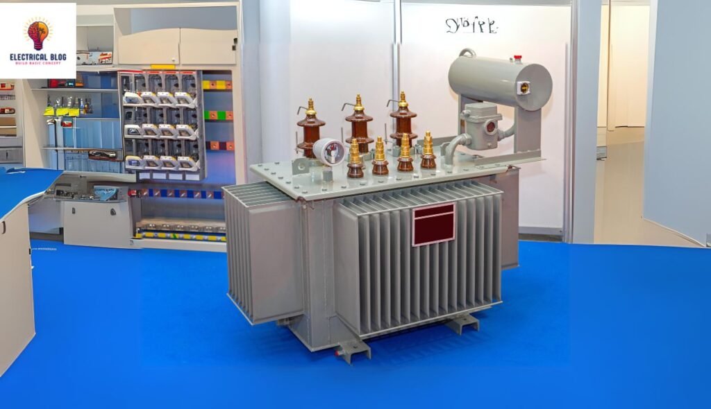
In power systems, PTs are installed in substations and other high-voltage areas. They ensure reliable voltage measurements for protective relays, meters, and control devices. This ensures both operational efficiency and safety. Without PTs, it would be hard to measure or monitor high voltages. This is vital for the power grid’s stability and for protecting sensitive equipment.
Working Principle of Potential Transformers
Potential Transformers (PTs), or Voltage Transformers, step down high voltages. They make the voltage safe for measurement and protection systems. This process is crucial for monitoring and protecting high-voltage systems in power grids.
Transformation Process
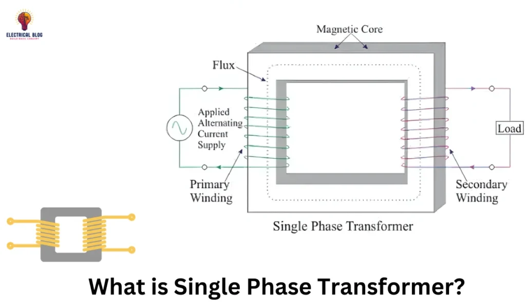
The electromagnetic induction concept underlies the operation of a potential transformer. This is the same as other instrument transformers. The PT’s primary winding connects to the high-voltage line. Its secondary winding connects to a low-voltage measuring device. This setup allows the PT to step down the high voltage proportionally to a safer level.
In a typical PT, the primary winding has a much higher voltage than the secondary winding. The turns ratio between the primary and secondary windings determines the voltage reduction. This reduced voltage is fed into meters or relays. They monitor and control the system. This allows for accurate voltage measurement. It avoids exposing equipment or operators to dangerous high-voltage levels.
PTs have high-quality cores. They operate at low flux densities. This ensures minimal errors during voltage transformation and boosts system reliability.
Construction of Potential Transformers
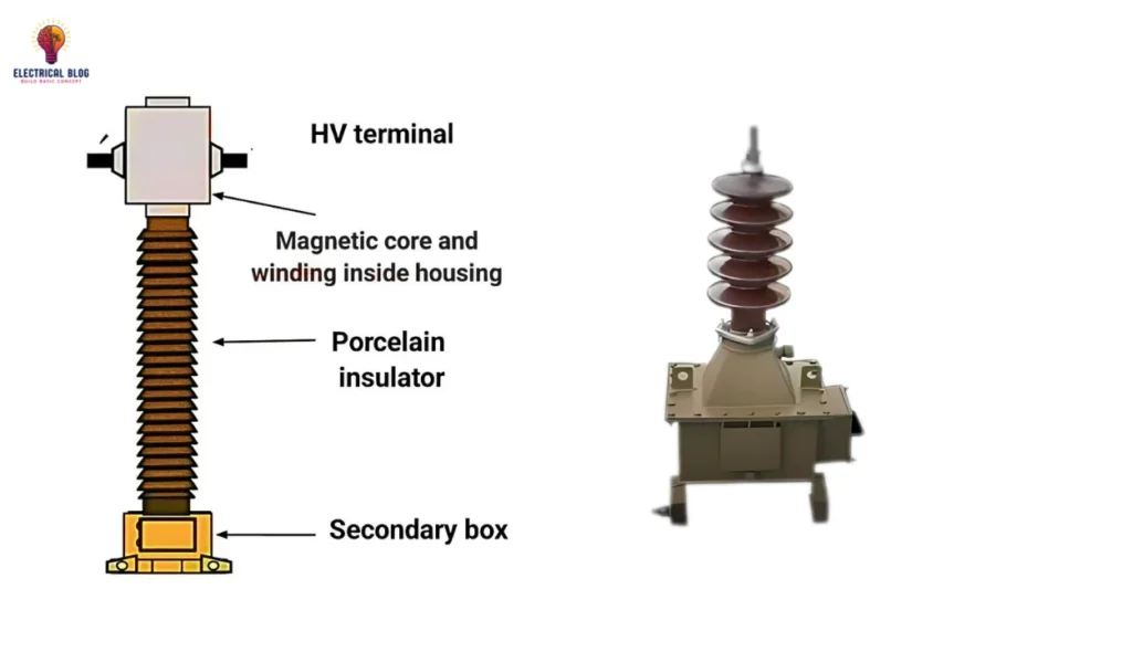
A Potential Transformer (PT), or Voltage Transformer, is an instrument transformer. It steps down high voltages to safe, measurable levels for metering and protection in power systems. A PT has three key components: the primary winding, the secondary winding, and the core.
Key Components
Primary Winding: The primary winding is connected to the high-voltage line. It has a few turns of thick, insulated copper wire. It is made to securely withstand high voltages. The primary winding creates a magnetic field. The secondary winding experiences voltage as a result.
Secondary Winding: The secondary winding has many more wire turns than the primary. It steps down the high voltage to a safe level. This can be used by measuring instruments like voltmeters or relays. The wire in the secondary winding is thinner because it carries less current.
Core: A PT’s core is usually laminated silicon steel. This minimizes energy losses from eddy currents. The core provides a path for the magnetic flux generated by the current in the primary winding. Its laminated design cuts power losses and boosts the transformer’s efficiency.
Specifications and Materials
Potential transformers usually use high-quality insulation and materials. They use copper or aluminum for the windings and silicon steel for the core. The windings allow for precise transformation. The insulation ensures safe, high-voltage operation. Typical voltage ratios range from hundreds of kV on the primary side to standard low-voltage levels on the secondary side.
Types of Potential Transformers
Potential Transformers (PTs), or Voltage Transformers, step down high voltages to safe levels in power systems. There are two main types of PTs: electromagnetic and capacitive. Each has a unique construction and application.
Electromagnetic PTs
Electromagnetic PTs operate on the principle of electromagnetic induction. They consist of primary and secondary windings wound around a magnetic core. These PTs are used in high-voltage systems. They transform high voltages into lower ones. This allows measuring instruments, like voltmeters and relays, to operate safely. Their construction requires high-quality insulation, especially in the primary winding. It must handle the high voltage. Electromagnetic PTs are the conventional type. They are widely used for their accuracy and reliability.
Capacitive PTs
CPTs use capacitors to step down voltage. They are for very high-voltage applications, like transmission lines. CPTs use a series of capacitors to reduce the voltage. This divides the voltage before secondary equipment measures it. They do not rely on magnetic induction. These are often used in systems where insulation and cost are key. CPTs can be cheaper than electromagnetic PTs. Capacitive PTs are ideal for high-voltage transmission systems. They offer a cheap, efficient way to measure voltage.
Connection of Potential Transformer
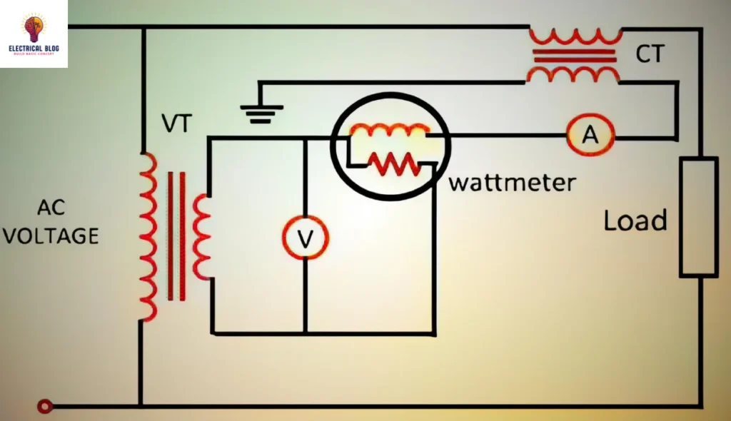
A potential transformer (PT) is connected in parallel with the power circuit. Its voltage is to be measured. The PT’s primary winding connects directly to the high-voltage power line, usually between the phase and ground. The secondary winding connects to voltage-measuring devices, like meters and relays. They safely and accurately measure the stepped-down voltage. This connection ensures the PT reduces high voltages to safe levels for monitoring and protection.
Errors in Potential Transformers
Voltage Ratio Error
An ideal potential transformer would have perfectly proportional primary and secondary voltages. However, practical limitations lead to errors expressed mathematically as:
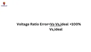
Where Vs is the measured secondary voltage and Vs,ideal is the ideal secondary voltage.
Phase Angle Error
The phase angle error is the difference between the secondary and primary terminal voltages. It arises from voltage drops in the circuit and can be expressed as:
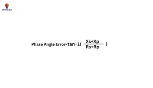
This error increases with the number of instruments connected to the secondary.
Burden of a Potential Transformer
The burden of a potential transformer (PT) is the load on its secondary winding. It is measured in volt-amperes (VA). It represents the load from connected devices, like meters or relays. The burden affects the transformer’s accuracy and performance. The PT must operate within its rated burden to maintain its specified accuracy.
For example, a rated burden might be 50 VA. This means the PT can accurately operate with a connected load of up to 50 VA on its secondary side. Exceeding the rated burden can cause voltage transformation errors. It can also affect the accuracy of measurement and protection devices.
Potential Transformer Phasor Diagram
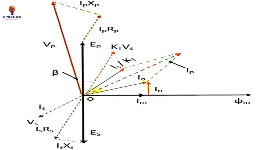
The phasor diagram of a potential transformer (PT) illustrates the relationship between the primary and secondary voltages and currents. In this diagram:
- Primary Voltage (VP): Represented as a reference phasor.
- Secondary Voltage (VS): This is typically a scaled-down version of the primary voltage, and it remains in phase with the primary voltage under ideal conditions.
- Primary Current (IP): The current drawn by the primary winding is very small, approaching the no-load condition.
- Secondary Current (IS): It flows through the load connected to the secondary side and is also in phase with the secondary voltage.
The phasor diagram shows that the primary and secondary voltages are in phase, while the primary current is close to zero, indicating minimal losses in the transformer under no-load conditions.
Applications of Potential Transformers
Role in Voltage Measurement and Monitoring in Power Systems
Potential transformers (PTs), or voltage transformers, measure high voltages in power systems. They are vital for monitoring these voltages. High voltages are stepped down to safety levels by them. This ensures that electrical systems can be monitored without risking equipment or personnel. This is vital for controlling voltage in transmission and distribution systems. Precise voltage measurements are needed to maintain stability and efficiency.
Use in Metering and Protection Systems
PTs are essential for metering and protection systems. In metering, they ensure accurate measurement of electrical parameters, like voltage. This is vital for billing and energy management in large power systems. PTs are also used in protective relays. They detect abnormal conditions, like over- or under-voltage. PTs send signals to help protective devices. They take actions, like isolating faulty sections, to protect the system.
Practical Applications in Transmission and Distribution Networks
In transmission and distribution networks, PTs monitor and control voltages over long distances. They are widely used for this. For example, they are installed at substations to lower high transmission voltages. This makes monitoring and protecting the system safe. It protects expensive equipment and keeps the grid infrastructure working. This prevents failures that could cause blackouts.
Advantages of Potential Transformers
Accurate Voltage Measurement for Power System Stability
A key advantage of potential transformers (PTs) is their accuracy in measuring voltage. These transformers reduce high voltages to safer, lower levels. They preserve the correct ratio, ensuring precise measurements. This accuracy is vital for power system stability. Control systems need exact voltage values. They use them to regulate power flow, prevent overloads, and optimize efficiency. Inaccurate readings could lead to system imbalance or failure.
Safety Benefits in High-Voltage Systems
Safety is another crucial advantage of PTs. PTs protect people and equipment in high-voltage areas. They do this by stepping down high voltages to safe levels. In power systems, voltages can be very dangerous. PTs allow monitoring and measurement without risking electrical shock or equipment failure. This is vital to prevent accidents and ensure system reliability.
Challenges and Limitations of High-Voltage Systems
Accuracy is limited at very high voltages
One of the main challenges in high-voltage systems is maintaining precise accuracy. As voltage levels rise, accurate measurements become harder. This is due to the non-linear behavior of electrical components at high voltages. These accuracy limits can affect the system’s reliability. They may cause issues in power distribution and control. Voltage stability analysis often struggles without a precise model. This makes high-voltage systems prone to errors in measurement and control.
Potential Failure Modes and Maintenance Requirements
High-voltage systems are also susceptible to various potential failure modes. These failures can be due to insulation breakdown, overheating, or external conditions. Regular maintenance is crucial to prevent failures. Neglected systems degrade, reducing efficiency and safety. Good maintenance reduces risks with high-voltage equipment. It ensures reliability and performance over time.
Difference Between Potential Transformer and Current Transformer
In power systems, Potential Transformers (PTs) and Current Transformers (CTs) are vital. They are electrical measurement devices. It’s vital to know their key differences. They are in function, construction, and application. This knowledge aids efficient electrical design and management.
Function
Potential transformers step down high voltages to a lower level. This makes them suitable for voltage measurement and control. They accurately show the circuit’s voltage. This ensures safe, reliable monitoring of electrical systems.
In contrast, current transformers focus on measuring the current flowing through a conductor. They reduce high currents to a lower, measurable value. This allows safe, contactless monitoring of current levels in high-power circuits.
Construction
The construction of PTs and CTs differs significantly due to their respective functions. Potential transformers typically have two windings. The primary winding connects to the high-voltage source. The secondary winding delivers the stepped-down voltage. This design allows for precise voltage measurement.
On the other hand, current transformers have a core. The conductor passes through it. The conductor itself forms the primary winding. The secondary winding is wound around the core. This design lets CTs accurately measure the magnetic field from the current flow.
Application
Potential transformers are mainly used in power distribution systems. They are for voltage monitoring, metering, and protection. They are vital for keeping electrical equipment at safe voltage levels.
Conversely, current transformers are extensively used in protective relays and energy metering systems. They provide feedback for monitoring and controlling electrical loads. This helps to prevent overloads and system failures.
Conclusion
Potential Transformers (PTs) are vital in power systems. They measure high voltage levels. This is key for safely operating and monitoring electrical grids. They reduce high voltages to manageable levels. This allows for precise voltage measurement and control in power networks. This ensures electrical equipment works safely and efficiently. It prevents damage from overvoltage. PTs help protect and ensure the reliability of electrical systems. They do this by providing real-time feedback on voltage levels. This enables operators to quickly respond to any network anomalies.
Looking ahead, the future of PT technology is poised for significant advancements. As energy demands grow, we need better, greener, and more flexible transformers. New materials and designs should improve potential transformers. They will be better at monitoring system performance and safety. Also, adding smart tech and IoT to PTs may boost their functions. It could allow for better data collection and analysis. These developments will enhance PTs’ roles in current power systems. They will also enable their use in the new smart grids and renewable energy systems.

