Introduction
Today, electricity powers our lives through countless appliances and systems. However, we must ensure the safety of these electrical systems. This is to prevent hazards like electric shock and fire. Neutral grounding is a vital safety measure. It protects equipment and people from electrical faults. This guide explores neutral grounding. It covers its principles, systems, standards, and applications. It provides details on how it ensures electrical safety.
What is Neutral Grounding?
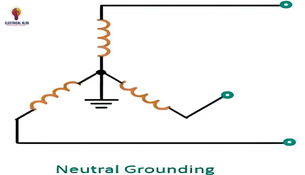
Neutral grounding means connecting an electrical system’s neutral point to the ground. This practice is vital. It protects power grids and prevents faults that could be unsafe. A reliable link between the neutral and ground can manage fault currents. It keeps electrical installations safe.
Key Features of Neutral Grounding
Enhanced Safety: Neutral grounding protects people from electric shock. It does this by safely conducting fault currents to the ground. This lowers the risk of dangerous voltages on metal and other conductive parts.
Fault Management: Neutral grounding provides a path to safely ground fault currents. It does this in case of an insulation failure or short circuit. This prevents equipment damage and reduces the risk of electrical fires.
System Protection: Neutral grounding connects the neutral point to the ground. It improves the reliability and safety of electrical systems. It ensures that protective devices, like fuses and circuit breakers, work effectively.
Methods of Neutral Grounding Systems
There are several types of neutral grounding systems. Each meets specific safety and operational needs. The choice of system depends on the type of installation and the required safety level.
TN-C Neutral Grounding System
The TN-C system is one of the older neutral grounding methods. It combines the protective earth (PE) and neutral (N) conductors into a single one, the PEN conductor. This system is generally used in three-phase power mains. Now, it is outdated due to its limited safety features. It is no longer used in new installations.
Key Characteristics:
The PEN conductor is used throughout the system.
It is not suitable for single-phase distribution networks.
Modern safety standards have rendered it obsolete for new constructions.
TN-C-S Neutral Grounding System
The TN-C-S system improves on the TN-C system. It separates the PEN conductor into PE and N conductors. This is at the point where a three-phase line branches into single-phase lines. This separation improves safety. It provides a better path for fault currents and reduces the risk of electric shock.
Key Characteristics:
Separation of PEN into PE and N conductors at branching points.
Higher safety levels compared to the TN-C system.
Suitable for single-phase networks with improved reliability.
TN-S Neutral Grounding System
The TN-S system is considered the most advanced and safest neutral grounding method. It requires a full separation of the neutral and protective conductors along the system’s entire length. This keeps all metal parts connected to the PE conductor. It provides strong protection against electrical faults.
Key Characteristics:
Full separation of neutral and protective conductors.
Enhanced safety through dedicated PE conductors.
Requires installation of a transformer substation with main grounding to avoid double grounding.
Types of Neutral Grounding Systems
Solid Grounding: In this method, the neutral point is directly connected to the ground. This is common in low-voltage systems where high fault currents are acceptable. Solid grounding ensures quick detection and disconnection of faults.
Resistance Grounding: A resistor is placed between the neutral point and the ground. This limits the fault current to a safe level. There are two types of resistance grounding:
Low-Resistance Grounding (LRG) limits fault current to high but manageable levels. It is often used in medium-voltage systems.
High-Resistance Grounding (HRG): This limits fault currents to very low levels. It’s ideal for systems that need to keep operating even during a fault.
Reactance Grounding: This uses an inductor, not a resistor, to limit the fault current. It is effective in controlling overvoltages during ground faults.
Arc Suppression Coil Grounding (Petersen Coil): It stops faults from causing dangerous arcs. It is commonly used in high-voltage systems where arc formation is a major concern.
Components of a Neutral Grounding System
A good neutral grounding system has several key parts. They ensure effective protection and reliable operation. Each component has a unique role. It must manage fault currents, enhance stability, and ensure safety. Here’s a detailed look at the key components:
Grounding Resistors
Grounding resistors are essential for limiting fault currents in a neutral grounding system. Their main job is to provide a path for fault currents to flow into the ground. This prevents excessive current that could damage equipment or create unsafe conditions.
Low-Resistance Grounding (LRG) resistors limit fault currents in systems. They keep them at moderate levels. They help balance fault current limits with system operation. This protects equipment while keeping the system running.
High-Resistance Grounding (HRG) Resistors: HRG resistors suit systems that need very low fault currents. This type of grounding is ideal for critical applications. It minimizes the faults’ impact on system operation, ensuring uninterrupted service.
Grounding resistors limit the fault current. They lower the risk of equipment damage and fire hazards. They also improve the electrical system’s safety.
Grounding Transformers
Grounding transformers provide a ground in systems without a natural one. They are vital for balancing the electrical system and for fault protection.
Wye-Delta Transformers: These transformers connect one winding in a wye (Y) and the other in a delta (Δ). This creates a neutral point. They are often used to enable neutral grounding and manage unbalanced loads.
Zig-Zag Transformers: They ground the system and manage unbalanced loads in high-voltage systems. They are especially effective in reducing harmonic currents and improving system stability.
Grounding transformers are vital. They provide a voltage reference, manage faults, and boost reliability.
Protective relays and monitoring equipment
Protective relays and monitors are vital for detecting system faults. They help keep the system stable and quickly isolate faults.
Protective relays: these devices monitor electrical parameters such as voltage, current, and frequency. They trigger circuit breakers to isolate faults and prevent damage. Relays are essential for quick and accurate fault detection.
Monitoring Equipment: These devices monitor the grounding system’s performance and health. They run continuously. They provide real-time data on system parameters. This allows for proactive maintenance and early issue detection.
Protective relays and monitors work together. They quickly find and fix faults. This minimizes damage and keeps the electrical system safe and reliable.
Grounding conductors and electrodes
Grounding conductors and electrodes carry fault currents into the earth. They are crucial for the grounding system. It must work and safely dissipate fault currents.
Grounding Conductors: They connect the system’s neutral point to the grounding electrodes. They must be sized to handle the fault currents. They must provide a low-resistance path to ground.
Grounding Electrodes: These are buried components, like rods or plates. They connect the electrical system to the earth. They help disperse fault currents safely into the ground.
Proper installation and maintenance of grounding conductors and electrodes are vital. They ensure the neutral grounding system works effectively. They safely conduct fault currents away from equipment and people. This reduces the risk of electrical hazards.
Ensuring Electrical Safety with Neutral Grounding
Effective neutral grounding is essential for maintaining electrical safety. We must consider several factors. They ensure the system is safe and reliable.
Importance of Adequate Short-Circuit Currents
For neutral grounding to work, the short-circuit current must be high. It must trigger protective devices, like circuit breakers or fuses. If the short-circuit current is too low, it may not manage fault currents. This can raise voltage levels and increase the risk of electric shock.
Key Recommendations:
Ensure short-circuit currents are adequate to activate protective devices.
Regularly inspect and maintain the condition of neutral conductors.
Avoid installing protective devices on neutral conductors.
Compliance with Safety Standards
Neutral grounding systems must comply with stringent safety standards to ensure reliable operation. Key standards are the Electrical Installations Code (PUE), GOST R 50571.5.54-2013, and GOST 12.1.030-81. These standards ensure the system works well and is safe.
Important Standards:
Electrical Installations Code (PUE), Section 1.7.
GOST R 50571.5.54-2013 (para. 543).
GOST 12.1.030-81 (para. 7).
Measuring and Maintaining Resistance
It is vital to measure and maintain resistance levels in neutral grounding systems. This ensures they work properly. This includes checking the resistance of neutral grounds and re-grounds. It also includes testing automatic protection devices.
Key Measurements:
Resistance of neutral grounding and re-grounds.
Time for automatic protection device activation in response to short-circuit currents.
Use a voltmeter-ammeter for accurate measurements.
Recommendations for Re-Grounding
To enhance safety, neutral grounding systems should be equipped with effective re-grounding mechanisms. Keep the resistance under 30 ohms per 200 meters of lines and poles. This will ensure effective fault management.
Re-Grounding Recommendations:
Maintain low resistance values for re-grounding systems.
Use natural ground electrode systems to achieve the desired resistance levels.
Neutral Grounding Standards and Regulations
Neutral grounding must meet standards and regulations. This ensures safety and effectiveness. These standards detail the technical requirements for neutral grounding systems. They cover their arrangement and maintenance.
Technical Requirements
The technical requirements for neutral grounding are specified in several regulatory documents, including:
Electrical Installations Code (PUE), Section 1.7.
GOST R 50571.5.54-2013 (para. 543).
GOST 12.1.030-81 (para. 7).
They detail limits on disconnection times, areas for conductors, and grounding resistance.
Key Technical Requirements:
Maximum disconnection times for different voltage levels.
Minimum cross-sectional areas for protective conductors.
Resistance limits for neutral grounding systems.
Disconnection Time Standards
For neutral grounding systems, the allowed disconnection times depend on the phase voltage. These standards ensure that damaged mains are quickly disconnected. This minimizes safety risks.
Disconnection Time Standards:
Rated Phase Voltage (V) | Maximum Disconnection Time (s) |
---|---|
127 | 0.8 |
220 | 0.4 |
380 | 0.2 |
More than 380 | 0.1 |
Cross-Sectional Areas for Protective Conductors
Protective conductors must have a specific cross-sectional area. This is to ensure effective grounding and fault management. These requirements vary based on the material and size of the phase conductors.
Disconnection Time Standards:
Rated Phase Voltage (V) | Maximum Disconnection Time (s) |
---|---|
127 | 0.8 |
220 | 0.4 |
380 | 0.2 |
More than 380 | 0.1 |
Applications of Neutral Grounding
Neutral grounding is used in many settings. It ensures the safety and reliability of electrical systems. Its use is critical in industrial and high-risk areas. There, electrical safety is paramount.
Industrial Facilities
In industry, neutral grounding is vital. It protects electrical systems and keeps people safe. These facilities often use generators or transformers for power. They need strong grounding systems to manage fault currents and prevent electrical hazards.
Key Applications:
Power sources, like generators and transformers, are essential.
Electrical installations with high safety requirements.
Facilities requiring enhanced noise immunity and fault management.
Residential Buildings
In residential buildings, neutral grounding is rare. But it is needed in some cases. Modern appliances often have three-pin plugs. They connect to a ground electrode system. This eliminates the need for neutral grounding. However, older buildings may need to modernize their outdated grounding systems. Only specialized electrical companies can do this.
Residential Considerations:
New housing developments use centralized grounding.
Older buildings may require upgrading or modernization of grounding systems.
DIY grounding in residential settings is discouraged due to safety risks.
Advantages and Disadvantages of Neutral Grounding
Like any technology, neutral grounding systems come with their pros and cons.
Advantages:
Improved safety: Grounding reduces the risk of electric shock and protects personnel.
Easier fault detection: A grounded system makes it easier to find ground faults. This allows for faster repairs.
Reduced equipment damage: By controlling fault currents, grounding prevents damage to sensitive equipment.
Disadvantages:
A grounding system makes electrical systems harder to design and maintain.
Cost: Grounding components, like resistors and transformers, raise the system’s cost.
Neutral Grounding vs. Protective Grounding
Neutral grounding and protective grounding both aim to improve electrical safety. But they differ in their methods and uses. Understanding these differences helps in choosing the appropriate grounding method for specific systems.
Purpose and Method
Neutral grounding aims to prevent electric shock and manage fault currents. It does this by disconnecting damaged installations from the mains. Protective grounding connects electrical installations to the ground. It reduces touch voltage and safely directs excess current into the soil.
Comparison:
Neutral Grounding: Disconnects damaged installations, enhancing safety in systems with dead-grounded grids.
Protective grounding: It reduces touch voltage. It also provides a path for excess current to the ground.
Application Patterns
Neutral grounding is used in systems with PEN, PE, or N conductors, such as TN-C, TN-S, and TN-C-S systems. Protective grounding is for insulated neutral mains (TT and IT systems). It adds protection by grounding individual parts of the system.
Application Patterns:
Neutral Grounding: TN-C, TN-S, TN-C-S systems.
Protective Grounding: TT and IT systems.
Neutral Grounding in Electrical System Design
Integrating neutral grounding into electrical design is key. It boosts system reliability and safety. Key points are: the grounding system choice, safety standard compliance, and regular maintenance.
Role in Electrical System Design
Neutral grounding is vital. It ensures safety and reliability in system design. It provides a path for fault currents, reducing the risk of electrical shock and fire. Good design means using the right grounding system. It also means meeting relevant standards.
Design Considerations:
Selection of the grounding system is based on system type and safety requirements.
Compliance with safety standards and regulations.
Regular maintenance and inspection of grounding systems.
Compliance with Standards
Standards are vital. They ensure neutral grounding systems work and are safe. Regular reviews and updates to grounding systems help. They ensure compliance and improve reliability.
Compliance Steps:
Regularly review and update grounding systems based on current standards.
Conduct inspections and tests to ensure system performance.
Implement recommended practices for grounding and fault management.
Conclusion
Neutral grounding is key to electrical safety. It protects against faults and hazards. A grasp of neutral grounding can help electrical engineers and safety experts. It includes its principles, systems, and standards. It can ensure the reliability and safety of electrical installations. Best practices and compliance with standards are key. They ensure effective neutral grounding and protect electrical systems.