What is a current transformer?
In electrical systems, managing high voltage and current is crucial for safety and performance. A current transformer is a special instrument designed to reduce large alternating currents into small, standardized values, making them easier to measure and monitor. These transformers work by isolating the primary side from the secondary circuit, ensuring that sensitive protective instruments remain safe from dangerous surges. Widely used in industrial, commercial, and power distribution networks, they play a vital role in substations, generating stations, and other electrical setups.
By accurately scaling values, they allow relays and monitoring units to function effectively without imposing a negligible load on the system. Their sensing ability ensures reliable measurement, and their potential to maintain accuracy makes them indispensable in power management. The type of CT chosen depends on its application, whether for protection or measurement, ensuring seamless integration into circuits. With their role in multiplying safety and efficiency, current transformers remain essential for stable AC power networks.
Working of a Current Transformer
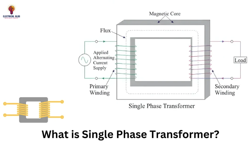
A current transformer works by using the principle of electromagnetic induction to convert high AC current into a smaller, measurable value. It consists of a core, a primary winding, and a secondary winding. The primary side, which carries the high current, is often a single conductor that is passed through the aperture of the CT. Some designs use a permanent bar, while others are window-type, allowing circuit cables to go through the opening. The magnetic field generated in the core induces a proportional current in the secondary side, which is then measured using an ammeter. The accurate transformation of current depends on the number of turns in the secondary winding, ensuring the output remains within the required range.
For efficient operation, the CT must meet specific requirements, such as proper coupling between the primary and secondary to maintain precision. The physical properties of materials like silicon steel and copper play a crucial role in enhancing efficiency. The illustration of a standard CT often shows elements like B, N, and I, which represent magnetic flux, the number of turns, and the current ratio, respectively.
The right placement of the conductor within the aperture ensures minimal insertion effects. Depending on the application, the design can differ, with variations in the core material, wire type, and insulation. These principles ensure the transformer delivers precise measurements for monitoring voltage, protection systems, and electrical circuits in a wide range of industrial uses.
In my experience, choosing the right current transformer depends on its application, accuracy, and design. One key factor is the ratio between the primary winding and secondary winding, which determines the transformation of current. For instance, a 4000:5 CT means that when 4000 amperes flow in the primary, the secondary delivers 5 amperes. The impedance on either side can be calculated using formulas like ZS = NZP or VS = NVP, ensuring proper performance in different electrical systems. Some models come with multiple taps to provide a range of ratios, making them adaptable for various metering needs.
The design of a current transformer varies depending on the manufacturer and end-user requirements. Low-voltage models are often molded in plastic cases, while split-core transformers have a removable section, allowing installation without disconnecting the conductor. Some are battery-operated, making them portable and ideal for hand-held measuring instruments. The core can be a single solid piece or a ring type, while certain switchgear applications use low-voltage units with standardized shapes. In industrial settings, precise secondary impedance ensures stability, especially when referring to initial values or adjusting for N2ZP calculations.
Types of Current Transformers
Wound Current Transformer
A wound current transformer has its primary winding in series with the conductor that carries the current to be measured. The primary consists of multiple turns, and its magnitude is dependent on the circuit it is connected to. The current flowing through the primary winding induces a proportional current in the secondary winding, maintaining a specific ratio. This design ensures accurate measurement and protection, making it ideal for applications requiring precise current monitoring.
Toroidal Current Transformer
A toroidal current transformer has a circular shape with a hole in the center, allowing the line that carries current to pass through without a primary winding. This design ensures smooth current flow in the circuit while being securely attached to the system. Some current transformers feature a split core, making installation easier by allowing them to be installed or closed around conductors without disconnecting the network. The conductor is simply threaded through the window, enabling accurate measurement and protection.
Bar-type Current Transformer
A bar-type current transformer uses a bus-bar or cable as its primary winding, acting as a single turn in the main circuit. It is fully insulated to handle high operating voltage, ensuring safety and efficiency. The current-carrying device is securely bolted to the system, providing a stable connection for accurate measurement and protection. This design makes it reliable for industrial and power distribution applications.
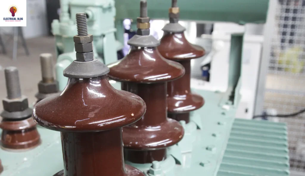
Structure and Components
A current transformer typically has a primary and secondary winding, with the primary winding connected to the circuit carrying the measured current. The secondary winding provides the output current proportional to the primary current. Split-core designs are common, where the transformer is made with a laminated iron core and hinged sections. This allows the transformer to be easily installed over a conductor or cable without disconnecting the circuit. The core links the magnetic flux generated by the primary winding to the secondary winding, ensuring accurate measurement of current.
To enhance protection and ensure accuracy, shielded designs often include a metal or plastic case around the transformer, with bushings or porcelain elements to handle high-voltage installations like those in a substation. Some transformers have multiple taps on the secondary winding to allow for different ratios based on the load and circuit requirements. The shielding provides safety by preventing any leakage of flux or unintended flow of current. Split-core transformers are also often used for overcurrent and differential protection in power and measurement applications, offering flexibility for different installation needs.
Uses of Current Transformers
A current transformer plays a crucial role in measuring and monitoring the flow of supply current in electrical systems, ensuring safe and accurate readings. In industrial and commercial setups, it helps in revenue metering, working alongside a watt-hour meter to track energy consumption. The National Electrical Code (NEC) mandates the use of protection devices like ground fault circuit interrupters (GFCIs) in residential areas, especially in wet locations such as bathrooms and kitchens. These devices function by detecting positive net current flow using a trip device, which triggers if the neutral return conductor does not balance the energized conductor, preventing potential hazards.
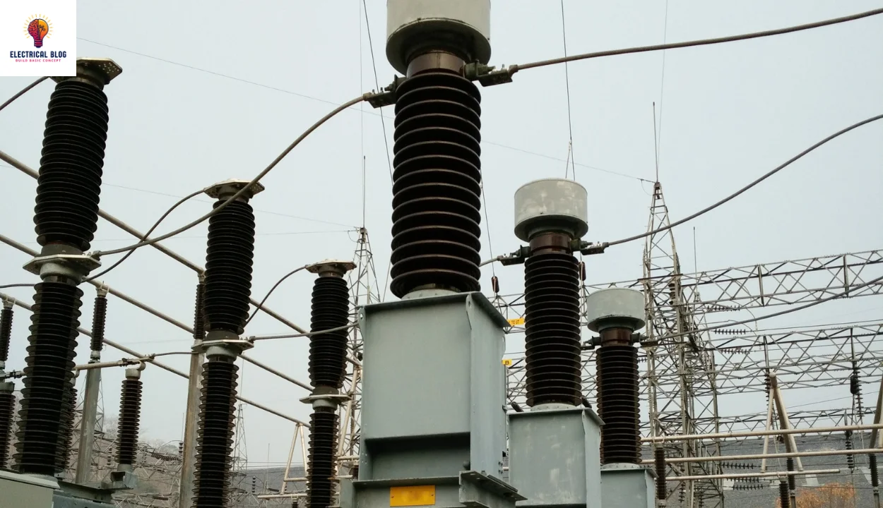
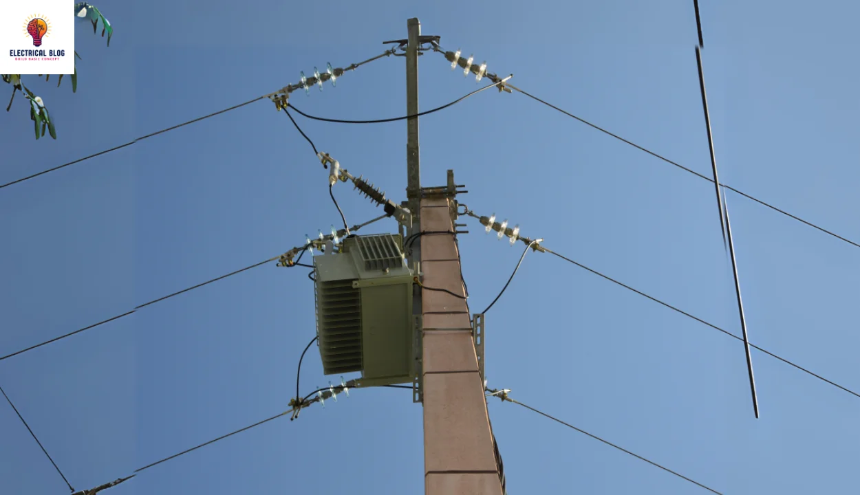
In high-voltage applications, current transformers are often found in power transformers, mounted on porcelain or polymer insulators to isolate them from earth ground. Some configurations slip around the bushing of a circuit breaker, centering the conductor within the CT window. When used in stack formations, they serve different functions, from protection to revenue-grade metering. However, exceeding the primary current rating or maximum value of the burden can cause saturation in the core, pushing it into a non-linear region, leading to a compromise in accuracy.
In power distribution, CT configurations may be applied in both low-voltage and high-voltage systems, sometimes requiring a busbar section to be removed for replacement. Impedance mismatches must be avoided to prevent excessive secondary voltage, which can damage connected devices. Outdoor applications, such as weatherproof power setups, rely on CTs to maintain efficiency, even in opposite directions of circuit wires. Quick response times, often within 0.2 seconds, ensure that a fault can be detected downstream, allowing the trip device to de-energize circuits before severe damage occurs.
Safety
Working with high electrical currents requires strict safety measures, especially in installations where a current transformer is used. One critical precaution is ensuring the secondary circuit is never disconnected while the primary is active, as this can lead to dangerously high voltages, sometimes reaching several kilovolts. If left open, the transformer attempts to continue generating current, which can cause arcing and potentially destroy components. This is why good design and adherence to industry standards are essential. Test of Current transformers are also essential.
The impedance of an open circuit must be avoided, as it can affect the accuracy of the output and even compromise the operator’s safety. The core experiences flux changes when loads are suddenly switched, creating fast transients that can induce dangerous spikes. While saturation limits excessive voltage in certain cases, it doesn’t eliminate risks. Proper practices dictate that systems be carefully monitored to handle variations in slope and prevent failures. Technical considerations, such as controlled burden and correct installation procedures, ensure stable operation and longevity of the equipment.
Accuracy of the current transformer
Ensuring the accuracy of CTs is essential for both measurement and protective applications. Various factors influence performance, including burden, impedance, and saturation levels. Industry standards, such as IEC 61869-1, define different accuracy classes, including 0.1, 0.2, 0.2s, 0.5, 0.5s, 1, and 3, each with a specific allowable error. For instance, a Class 1 CT maintains a ratio error within 1% at rated current, while a Class 0.5 has a tighter limit of 0.5% or less. The CT’s performance can also be affected by external fields, electromagnetic interference, and temperature changes, which impact the core and magnetizing properties. The configuration of the circuit, as well as the physical design, determines how well it operates under varying currents and load conditions.
In relaying applications, CTs must perform accurately even during excess fault currents. A CT with a rating of 2.5L400 ensures its secondary winding delivers 100 A at a 400 V drop, with an error margin within 2.5 percent. Proper measuring techniques account for phase shifts and changes in power levels, ensuring effective operation of relays in high-demand environments. The correct tap on a multi-ratio CT must be selected to match the specified application, maintaining precision and reliability in the system.
Burden
In a current transformer, the burden refers to the total impedance connected to its secondary winding, which impacts its accuracy and measurement performance. The circuit must handle the correct ratings, such as VA values or ANSI and IEEE burden classes like B-0.1, B-0.2, B-0.5, B-1.0, B-2.0, and B-4.0. A key challenge in metering applications is the resistance of conductors and the voltage drop across long cable runs, especially in substation settings.
Excessive lengths of wiring between cabinets and meters can lead to a higher burden, affecting phase accuracy. Using thicker cables and lowering Ω values can reduce these issues. Engineers use parallelograms on a grid with scales for magnitude and specification checks to ensure proper transformer operation. Switch blocks, intermediate connections, and other devices in the network should also be optimized for efficiency.
Advantages of Current Transformers
The current transformer offers several advantages that make it an essential device for various electrical applications. Known for its exceptional ability to measure and provide accurate and precise readings, it performs well under changing loads and conditions, making it reliable. It is used in multiple applications, from monitoring power consumption to protecting electrical equipment in renewable and industrial systems.
The electrical isolation between the primary and secondary circuits not only ensures safety but also prevents high currents from reaching measuring devices, safeguarding the whole system. Additionally, current transformers are long-lasting and robust, built to withstand harsh environmental conditions. Their easy installation and simple operation make them a go-to choice, and they are easy to maintain as well.
Conclusion
In summary, current transformers are essential for converting a primary current into a secondary current, providing accurate measurements in various conditions. The coil in these devices is often a toroidal, doughnut, or bar type, which ensures low voltage and safe operation. For accurate results, series transformers must be correctly powered, and open circuit situations should be avoided. Additionally, these devices must be short-circuited when not in use to prevent high voltages that could damage the system or other connected equipment like ammeters. The winding design and turns depend on the ratios needed, with common ratings being 1A or 5A. Overcurrent, undercurrent, and peak current are all monitored effectively, making these devices vital for reliable electrical measurements and proportional current applications.