Introduction
A center-tapped transformer plays a crucial role in many electrical systems, especially in full bridge rectifiers. By providing a center-tapped secondary winding, it allows for the conversion of AC voltage into DC power, which is essential for various applications like operational amplifiers and analog circuits. This transformer configuration enables the rectifier to use both positive and negative half-cycles of the input AC signal, ensuring complete wave rectification. The design also ensures that two equal voltage outputs are provided, making it ideal for creating a dual power supply and offering balanced output to reduce signal noise and distortion.
What is a center-tapped transformer?
A center-tapped transformer is designed with a special secondary winding that has a center tap, allowing it to divide the voltage into equal parts. This feature is highly advantageous for many applications, especially in rectifier circuits and power supplies, where a stable neutral point is required. In residential systems, it efficiently provides 120V from a 240V source, ensuring both low and high-voltage needs are met. The connection of the grounded center tap enhances safety and reliability.
Unlike a single output voltage transformer, a center-tapped one supplies opposite output voltages, each shifted by 180° phase. This configuration offers versatility, making it suitable for diverse electrical requirements in both industrial and household setups. By supplying power through this design, it ensures efficiency while enhancing overall performance. Whether for balanced loads or specialized circuits, this type of transformer remains a valuable component in modern electrical engineering. You can also read transformer parts.
Working Principle of a Center-Tapped Transformer
When alternating current is applied to the primary winding, it generates a magnetic flux in the core, which then links to the secondary winding. This inducing process creates an alternating magnetic flux, causing current to flow through the external circuit. The voltage in one part of the secondary winding is equal in magnitude but opposite in phase to the other part, effectively dividing the output into two halves. This design ensures stable power distribution and efficient energy transfer.
Structure and Design of a Center-Tapped Transformer
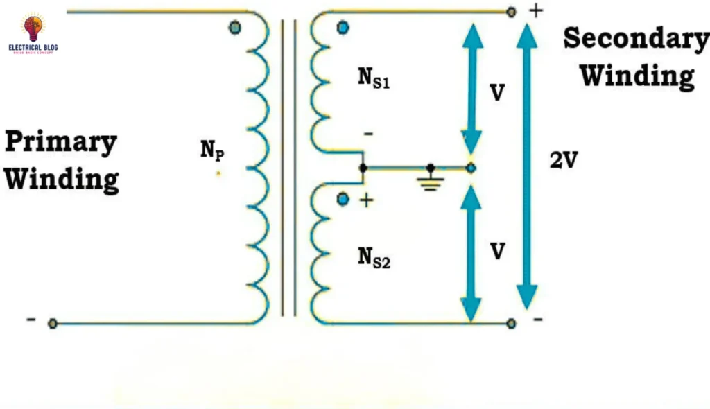
A center-tapped transformer is built with primary windings and secondary windings wrapped around an iron core, ensuring efficiency and reliability. The secondary is divided into equal halves, with a center tap at the central terminal, which acts as a common ground and a reference point for the circuit. The core, made of laminated steel sheets, helps in reducing eddy current losses, significantly improving performance. The windings are carefully wound around the core, enhancing its function and making it a vital component in various electrical applications.
Working of a Center-Tapped Transformer

When an AC supply is connected to the primary winding of a center-tapped transformer, a changing magnetic field is created around it. This magnetic field passes through the core, producing magnetic flux that induces a voltage in the secondary winding. According to Faraday’s law of electromagnetic induction, the induced voltages are divided into two equal parts due to the winding arrangement. The secondary coil consists of two sections, each having an equal number of turns, ensuring that:
NS1 = NS2
This means the output voltages on both sides remain balanced.
The flows of the induced voltage are denoted as VS1 and VS2, with one side being line 1 and the other line 2, while the neutral is at the center-tapped transformer point. The induced voltages in each second portion of the winding are represented as ES1 and ES2, following the equation:
ES1 = (NS1 Ep) / Np
ES2 = (NS2 Ep) / Np.
Similarly, the output voltage relationship is given by:
VS1 = (NS1 Vp) / Np
VS2 = (NS2 Vp) / Np
Ensuring VS1 = VS2. This balanced design allows for efficient power transfer while maintaining a stable reference point.
Center-Tapped Transformer Formula
In a center-tapped transformer, the voltages on both sides are dependent on the primary voltage and the turns ratio between the windings. The mathematical expression for this relationship is given as:
VS1 = (NS1/Np) × Vp
VS2 = (NS2/Np) × Vp
These output voltages are 180 degrees out of phase, meaning they have the same magnitude but flow in opposite directions. To bring them into the same phase, we often combine the transformer with a full-wave rectifier, ensuring a steady and balanced DC output.
Understanding the 12-0-12 center-tapped transformer
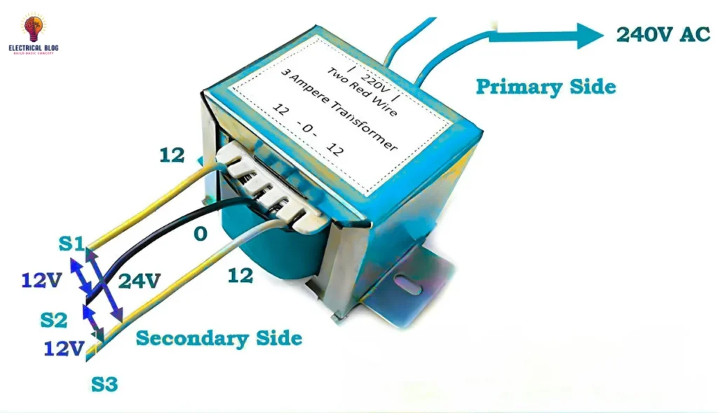
A 12-0-12 center-tapped transformer features a secondary winding with a center tap that divides the winding into two equal halves. The first “12” represents the voltage between the center tap and one end of the secondary winding, which is 12 volts. The second “12” indicates the voltage between the center tap and the other end of the winding, which is also 12 volts. This setup ensures that the voltages are equal and opposed, with the center tap serving as a reference point for both halves.
The total voltage across the entire secondary winding (from one end to the other) is the sum of the voltages on each half, which in this case is 24 volts. The center tap is typically grounded, providing a stable reference for the system. This transformer is commonly used in applications requiring a balanced voltage setup. The UL 5085-1 standard specifies the low-voltage transformer specifications for center-tapped transformers, ensuring that they meet safety and performance criteria.
12-0-12 Center-Tapped Transformer Specifications
This center-tapped step-down transformer has a vertical mount and operates with an input voltage of 220V AC at 50 Hz. The winding is made of copper, and it provides output voltages of 0V, 12V, and 24V, with an output current of 1 A. The 12V and 24V outputs are ideal for a variety of applications requiring stable power.
Additional center-tapped transformer
18-0-18 (1A, 2A, 3A, 5A) Center-Tapped Transformer
6-0-6 (1A, 2A, 3A, 5A) Center-Tapped Transformer
12-0-12 (2A, 3A, 5A) Center-Tapped Transformer
24-0-24 (1A, 2A, 3A, 5A) Center-Tapped Transformer
Where to Use Center-Tapped Transformers
Center-tapped transformers are commonly used in rectifier circuits, especially when a digital project requires AC power to be converted to DC. They are perfect for step-down applications, providing 24V or 12V output, and are widely employed in full-wave rectifier setups. This transformer is essential in circuits requiring high peak inverse voltage, such as in a two-phase three-wire transformer or bridge rectifier applications.
Advantages of Center-Tapped Transformer
A center-tapped transformer provides dual voltage outputs, making it ideal for applications requiring two-phase power. This design ensures equal voltage on both sides, perfect for use in full-wave rectifiers. By utilizing both halves of the AC cycle, it significantly improves the rectification process, enhancing the overall efficiency. This makes it highly beneficial for systems that demand better power conversion.
Disadvantages of Center-Tapped Transformers
An improper grounding of the center tap can lead to an imbalance between the two parts of the secondary winding, affecting proper operation and safety. This imbalance can compromise the transformer’s efficiency and reliability.
Applications of Center-Tapped Transformers
A center-tapped transformer is widely used in various applications, including operational amplifiers and analog circuits, where it provides a dual power supply with positive and negative supply voltages. It is ideal for complete wave rectification of AC power into DC power, as secondary windings help convert AC voltage into DC voltage with the help of a rectifier diode. Additionally, the center tap plays a crucial role in ensuring a balanced output to reduce signal noise and distortion in the amplifier. This transformer also provides galvanic isolation, which is essential for separating electrical circuits and preventing electrical interference.
What is a full-bridge rectifier with a center-tapped transformer?
A full bridge rectifier with a center-tapped transformer uses a center-tapped transformer to supply an AC signal to the rectifier circuit. The secondary winding of the transformer is connected to diodes at both ends, which allows the conversion of the AC voltage into DC power. This setup also provides two equal voltage outputs, making it ideal for systems requiring a dual power supply. The full bridge rectifier works by utilizing both the positive and negative half-cycles of the AC signal, ensuring complete wave rectification and reducing distortion.
conclusion
In conclusion, the center-tapped transformer is a key component in ensuring efficient power conversion, especially in applications like full bridge rectifiers. By utilizing both the positive and negative half cycles of the AC signal, it provides complete wave rectification and helps in reducing distortion. This transformer not only offers two equal voltage outputs but also ensures a balanced output, making it an ideal solution for dual power supply requirements in analog circuits and operational amplifiers. Additionally, its ability to reduce electrical interference and provide galvanic isolation makes it crucial for many electrical systems.


