Introduction
When working with electric systems in large industries, I’ve often seen how vital circuit breakers are in ensuring safety. Whether operated manually or remotely, their function is to break the circuit under abnormal conditions like overcurrent or short circuit faults. One key type I’ve worked with is the air circuit breaker, commonly used for protecting high-voltage devices.
These breakers are essential in controlling power flow across transformers, motors, generators, and alternators. They’re often associated with other devices like relays, switches, and fuses, each playing a part in system protection. This article gives a practical overview of their application, purpose, and where they’re used, namely in industrial systems and gear.
What is an air circuit breaker?
In modern electrical systems, the ACB is a trusted device for protection against overcurrent and short-circuit faults. Located in distribution panels under 450V, it is effective in low-voltage applications managing circuits from 800 to 10,000 amps. These are common in both industrial setups and commercial systems.
The Air Circuit Breaker works in open air, using natural atmospheric pressure as the interrupting medium to regulate the arc. It’s easy to install, maintain, and is known for being durable, high-performing, and oil-free—replacing the older oil types in the market. With several types, switching gears, and panels, this breaker makes working environments much safer.
Air Circuit Breaker Construction
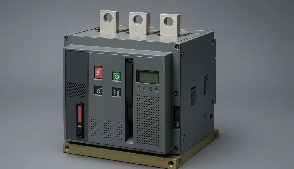
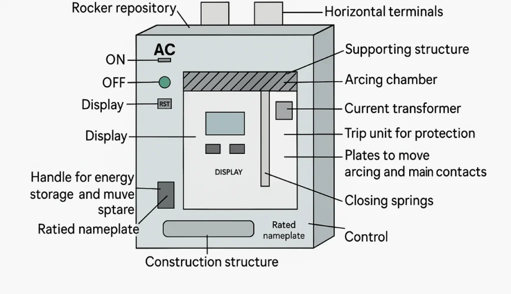
The assembly of an air circuit breaker has several internal and external components that collaborate to provide safety. From my fieldwork, I often check the ON/OFF button, LED indicators, RST, and nameplate to ensure clear position and fault signals. The controller, handle, rocker, and display help manage energy storage and quick-trip actions.
Inside the ACB, I’ve seen how the steel sheet structure, support, insulating box, and chamber ensure solid operation. Current transformers, terminals, plates, and springs are mainly used to protect and move the contacts. The control unit manages opening, closing, arcing, and connects horizontal terminals, pole groups, and repositories for smooth function.
Working Principle
The working principle of an Air Circuit Breaker is to stop arcing between contacts when the gap becomes wide enough to resist voltage recovery. Unlike other CBs, it operates using air at normal pressure as the medium for breaking the arc. Its function is critical in systems where overcurrent or short-circuit events could damage electrical circuits.
When the breaker opens, an arc is started between the contact points, and the arc voltage is increased using several methods. Cooling the plasma, splitting the arc, and extending the arc path are common methods to raise resistance. As temperature and particle motion reduce, more gradient becomes necessary to keep the arc flowing.
Inside the ACB, two sets of contacts are used—one major pair made with copper and another with carbon. Once the opening begins, the main contacts are divided, but the arc contact still stays connected until the arc extinguishes. The operating range is up to 1 kV, which fits low-voltage applications in distribution panels found below 450 V.
Air Circuit Breaker Working
In my experience with low-voltage circuit breakers, I’ve found that they operate with contacts in free air. The method of arc quenching here is quite different from older oil-based types. These breakers are designed for safe interruption during faults and are often used to replace high-voltage circuit systems.
When current flows through the main contact pairs, it is carried under normal load by a copper pair. A second pair made of carbon handles arcing when the contacts are opened. As the contact is opened, the arc is initiated and quickly moves upward due to thermal and electromagnetic forces.
The arc then enters the chute, which consists of splatter plates that help to lengthen and split the arc. This raises the arc voltage much higher than the system voltage, helping to finally extinguish the arc. These plates also guide the arc through resistive paths, making it easier to control.
Within the brake box, constructed from insulating and fire-resistant material, the arc is segmented into pieces. Each section is separated by barriers and includes a small metal conducting element for electrical continuity. This ensures the arc remains controlled as it passes through several paths in series.
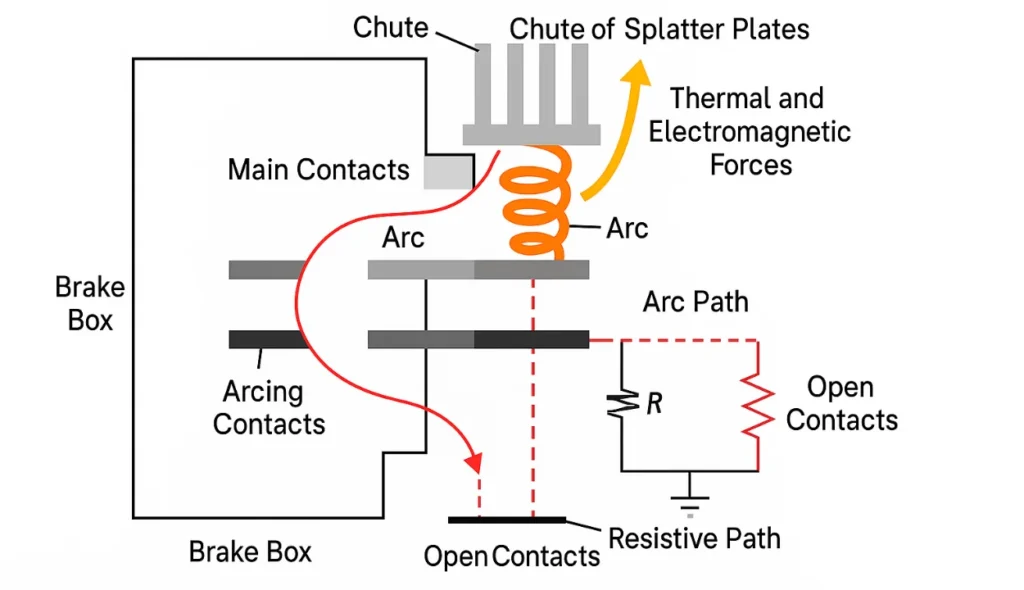
As the arc moves upward, it forms a helix within each section, helping to increase its length and resistance. These helices provide a more gradual current decrease, hence improving the functionality of the breaker. I’ve noticed this form is very efficient in controlling fault energy.
When the arc terminates at the current zero, ionized air persists in the pathway as a shunt. It runs in parallel with the open contacts, acting as resistance and absorbing the remaining energy. Aided by self-capacitance (C) and resistance (R), this setup stabilizes voltage fluctuations.
If oscillation begins between C and L, damping becomes critical. This stops any high-frequency oscillation and avoids restriking of the arc. Instead of spiking, the voltage rises deadbeat to match the peak generator voltage, which is often illustrated in waveform figures.
Types of Air Break Circuit Breakers
Plain Break type Air Break Circuit Breaker
The plain-type air circuit breaker is one of the simplest forms of breakers I’ve worked with in low-voltage applications. It has main contacts shaped like horns, where the arc stretches from one tip to another. The way the arc responds to interruption is another reason why this kind is known as cross-blast ACB.
The chamber or arc chute is surrounded by walls and separated into compartments using metallic plates called splitters. As the arc moves, it is divided into a sequence of smaller arcs across each mini-arc compartment, which helps in cooling. This makes the total arc voltage much higher when compared to the system voltage, enhancing breaking performance with refractory material inside the arrangement.
Magnetic Blowout Type Air Break Circuit Breaker
Air breakers of the magnetic blowout type are often used in systems that can handle voltages of up to 11 kV. They use the current through blowout coils to generate a magnetic field, which helps shift the arc away from the contacts. This design gives better control of arc extinction compared to older circuit breakers.
The circuit is disrupted when the arc is shifted into arc chutes, where it gets cooled and extended. These coils are connected in series and form part of the circuit connection. As the field pushes the arc, it supports clean interruption wherever needed without manual effort, as the name suggests.
Air Chute Air Break Circuit Breaker
The air chute-type circuit breaker is commonly designed for low-voltage applications and uses two kinds of contacts—main and auxiliary. The main contacts are made of copper and silver-plated to ensure low resistance and reliable current flow when closed. These contacts are placed in positions that allow them to conduct electricity in a solid connection.
The auxiliary or arcing contacts are designed with a copper alloy to be resistant to heat, helping to avoid harming the main ones during interruptions. When operating the breaker, the contacts are opened and closed in a proper sequence to handle the arcing safely. These plates can be changed if required, keeping the breaker easy to maintain. I have found their design to be smart and effective in high-use industrial locations.
Air Blast Circuit Breaker
The air blast circuit breaker is often used in high-voltage systems like 245 kV and 420 kV where quick operation is necessary. Its speed of breaking is high, making arc quenching much faster than in older oil types. Its ability to prevent fire threats and lower maintenance needs is one of its primary advantages.
When the arc duration is short, less heat is passed to the contacts, increasing their service life. System stability is well maintained as it depends on how fast the breaker reacts to currents and disruptions. These types include three main versions: axial, axial with sliding or moving contact, and cross blast, each suited to different voltage values.
Air Circuit Breaker Maintenance
ACBs are used as protection devices in low-voltage applications like UPS, generators, mini power stations, and MCCB distribution boards. They operate up to 600V AC and come in a range of sizes from 400A to 6300A or even larger. Without proper maintenance, these breakers can face failures due to dusty environments, grease, corrosion, or tough parts. Regular care helps to extend their lifetime and keep operations consistent.
Turning off the breaker and opening the electrical isolator is the first step in the maintenance procedure. It should be worked on electrically in restricted and distant areas once every year, and then mechanically to check sliding parts. This helps in detaching any developed layer on the face of moving elements and ensures smooth performance. In my field jobs, I’ve seen how caring for the outside of breakers keeps the system clean and reliable.
Air Circuit Breaker Testing Procedure
In my fieldwork, I’ve seen how testing a circuit breaker is essential to ensure secure operation and long-term performance. This process checks each switching system, programming, and construction through a series of routine tests. Compared to other devices, breaker testing is more challenging and must be performed with precision. It helps detect faults that may occur due to incorrect behavior or damage inside.
Typical tests include mechanical, thermal, and dielectric evaluations, along with trip tests and overload or instantaneous tripping. The magnetic response is also measured, as are resistance, insulation, and contact conditions. If coils or connections fail, it could harm the entire system, so testing must be done regularly. A complete test ensures the breaker performs well even under short-circuit pressure or in different fault types.
How can testing be performed?
In my hands-on work with breakers, testing is done using different methods and specialized equipment to verify the condition of the circuit breaker. Tools like analyzers, micro-ohmmeters, and primary injection testers with high current help test the system. These devices are used to check load, offload, and performance under various real-world situations.
The key benefits include enhanced performance, early indications of faults, and recognized issues that can be avoided. It also recognizes the requirement for maintenance before failure occurs. Every test ensures the breaker can handle power safely and efficiently when needed.
Advantages
High-speed operation is a major benefit, making these breakers ideal for modern protection systems.
They offer a reclosure facility, which means it can be used for frequent switching without failure.
The need for maintenance is less, saving time and reducing long-term service costs.
Fire risk is completely eliminated, unlike in traditional oil circuit breakers.
The arcing time is short and very consistent, ensuring efficient performance with minimal wear.
Burning of contacts is significantly less, which extends the life of the system.
Drawbacks
At low currents, when electromagnetic fields are too weak to propel the arc efficiently, the air circuit breaker’s arc chute concept becomes ineffective, which is one of its main disadvantages. The action of lengthening and deionizing is still efficient, but its impact is less noticeable under these conditions.
The movement of the arc becomes slower, so high-speed interruption is not always obtained. While it performs well at higher currents, its response during small faults may necessarily lag slightly, especially in systems that rely on fast switching performance.
Applications of Air Circuit Breakers
In power plants and industrial facilities, air circuit breakers are often employed to safeguard vital electrical equipment and regulate auxiliaries.
These breakers ensure protection in environments where fire or explosion hazards are possible, making them ideal for safety-focused applications.
By using strategies including splitting, cooling, and arc lengthening, the braking principle assists in controlling DC and AC circuits up to 12 kV.
With high resistance capability, they assist in increasing the resistance of the arc, reducing damage during faults.
Air circuit breakers are also used in electricity-sharing systems like NGD, especially where ratings approach 15 kV and a stable flow is required.
Conclusion
Air circuit breakers play a vital role in modern electrical systems, offering reliable protection, high-speed operation, and ease of maintenance across various industrial and commercial applications. Their ability to handle different fault conditions, control power flow, and provide safe interruption makes them a dependable solution in both low and high-voltage environments.
From plain break to magnetic blowout and air blast types, each variation of ACB serves specific needs with unique strengths. With regular testing, proper maintenance, and smart deployment in systems like distribution panels and electricity-sharing networks, air circuit breakers continue to be essential components in achieving system stability, safety, and performance.