Introduction
When dealing with electrical components, selecting the proper type of switch is important to ensure a reliable application. Among various circuits, the SPDT switch stands out due to its versatility. This switch allows a circuit to break or connect in different ways, making it suitable for multi-make and multi-break configurations. The mechanics behind its operation may seem simple, but when applied in the best way, it can enhance functionality.
Each design has its style, and the logic of how it functions should be well understood before being chosen for a project. Whether it’s about opening or closing a circuit, the ability to vary connections makes this switch highly effective. So, let’s look into different methods of using SPDT to get a better grasp of its working principles.
What is an SPDT switch?
An SPDT (Single Pole Double Throw) switch is a versatile component used to control electrical circuits. It consists of three terminals—an input and two output paths—allowing the current to flow in different directions. When applied, it can be set in an ON/ON configuration, meaning that at any given time, the connection between the input and one of the output terminals is always complete. If the switch is in the ON-1 position, the first circuit is established, while shifting it to ON-2 completes the second path. This style makes it useful for applications requiring a normally open or closed configuration, providing seamless switching between two states.
Some SPDT switches also feature a third mode, commonly referred to as ON/OFF/ON. In this setup, the switch can be turned OFF, where neither the first nor the second circuit remains complete. This type of switch is often directed by a roller or lever, which actuates its movement and determines the direction of the current flow. The mechanical design allows for smooth operation, and it is widely used in various pole-based switching systems. With its common usage in electronics, an SPDT switch provides a reliable way to manage voltage and complete a circuit as needed. You can also read Air Break Switch.
SPDT Switch Symbol

Key Parts of an SPDT Switch
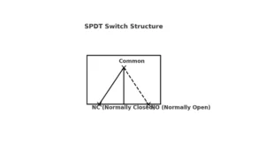
An SPDT switch consists of three terminals—one input and two outputs—which allow electricity to flow in different directions. Inside, the movable contact, often made of metal, is controlled by an actuator or knob, shifting the connection between the NO (normally open) and NC (normally closed) terminals. The common terminal remains connected at all times, serving as a bridge for electrical transfer. This structure ensures that the switch can efficiently manage power distribution while maintaining a steady state in a resting or operating position.
Beneath the input, the common contact is located underneath, ensuring proper connection. The switch works by pivoting the lever, shifting between the two output options. Proper labeling helps in recognizing the correct position, avoiding unwanted disconnection. The internal components are designed for durability, and their intermediary role ensures a smooth electrical flow between circuits. Understanding these components is crucial for the proper operation of an SPDT switch.

Advantages of SPDT switches
SPDT switches are known for their reliability and low cost, making them ideal for various applications. They can handle high voltages and higher currents, allowing them to control devices like pumps, relays, and motors. Their proven function makes them essential in switching operations for plant systems and drive mechanisms.
Applications of SPDT switches
An SPDT switch plays a crucial role in powering various electrical equipment by allowing users to select between two different paths of voltage. This makes it highly useful in household appliances and industrial systems. In motor control, an SPDT switch can reverse the polarity of a DC motor, effectively changing its direction.
For safety, these switches can detect dangerous conditions and deactivate machinery to prevent accidents. They also serve as selector switches in audio systems, enabling users to switch between pickup configurations, such as the bridge or neck positions on a guitar. Their versatile nature makes them ideal for controlling relays, light sources, and various electrical circuits.
In harsh conditions, SPDT switches are designed to resist external elements like dirt and debris, which can cause operational issues. Some models come with stiffer springs and engineered materials to improve durability and prevent malfunctions.
For example, in cold environments, frozen internals can become a problem, making off-the-shelf switches unreliable. By incorporating specialized construction details, these switches ensure better performance across a range of applications. Whether used for control circuits, selecting outputs, or managing electricity, an SPDT switch remains an essential component in modern electrical designs. You can also read Centrifugal Switch.
Wiring an SPDT switch
Wiring an SPDT switch is a straightforward process, but it is important to follow the correct steps to ensure a safe and efficient electrical connection.
The first step is identifying the terminals, which include one common, one NO (normally open), and one NC (normally closed). The power source connects to the common terminal, allowing the switch to direct current flow between the NO and NC terminals based on its position.
To complete the circuit, a wire must be soldered from the common contact to the power supply. The output device or load should then be connected to either the NO or NC terminal, depending on the desired function. The negative terminal of the power supply or grounding point must also be correctly linked to prevent failure or damage. Ensuring secure connections helps avoid potential short circuits or loose wiring that could disrupt the process.
When operating the switch, the setting determines whether the signal flows to the NO or NC terminal. If the switch is flipped to one position, the connection is made with the NO terminal, while switching to the other position establishes a link with the NC terminal. This function is useful for handling different devices that require alternate power points without manual rewiring.
Securing all cables is necessary to prevent exposed connections, which could lead to hazardous situations. A failure to properly insulate wires may result in electrical leaks, posing a risk of injury or even severe damage to the circuit. Proper measures, such as insulating materials and firm soldering, help ensure a safe and reliable setup.
After completing the wiring process, a test should be conducted to verify that the SPDT switch functions as expected. If any issues arise, checking for loose contacts, weak soldering, or incorrect connections can help resolve the problem. Taking caution during the installation and ensuring that all processes are done correctly will guarantee an efficient and long-lasting switch setup.
SPDT Switch Diagram

Switching Between Multiple Circuits
To control multiple circuits, an SPDT switch is used to manage different power connections. It allows for a secure and efficient way to transfer electricity between separate paths.
Start by identifying the input and output terminals on the switch and the circuits to be powered. The first circuit connects to the common contact, ensuring proper operation.
Soldering a wire from the input terminal to the common point is essential for safe connections. The NO (normally open) and NC (normally closed) terminals each connect to different circuits.
When the switch is in one position, it energizes one circuit while the other is deactivated. Toggling the switch allows an instant transfer of power between circuits.
It’s important to test the setup by flipping the switch to confirm the connections work properly. If the circuit does not work, check for loose wires or exposed joints.
To ensure a safe and hazard-free system, always verify the voltage and current ratings. A poorly rated switch can cause a short circuit or failure.
For additional safety, check that the handling of electricity is done with caution. Any open or exposed connections can be dangerous if not properly insulated.
Following a step-by-step guide helps keep the wiring process simple. A well-installed SPDT switch ensures smooth operation and reliable power control.
Troubleshooting Tips for SPDT Switch Wiring Issues
The first step in troubleshooting an SPDT switch is to check the wires and ensure they are firmly connected. A disconnected or exposed wire can cause a malfunction, affecting the overall function of the circuit.
Verify the placement of the switch, as an incorrect position can lead to unexpected issues. If the switch is not functioning as expected, double-check that it is properly positioned to avoid failure.
It’s essential to test the voltage and current with a multimeter to confirm they are within the specified limits. If the electrical parameters exceed what the switch can handle, there is a high probability of damage.
Look for shorts in the circuit, as these can lead to serious failures or even permanent damage. Identifying and fixing issues early helps to resolve potential risks before they escalate.
Use the right equipment to ensure a proper test of the connections. A multimeter is useful for measuring amperage and verifying whether all components are working as they should.
If the switch remains non-functional after all troubleshooting steps, a replacement may be necessary. Always ensure that the new switch meets the required parameters to guarantee smooth operation.
Following these tips in the correct order will help identify and resolve wiring problems effectively. Proper troubleshooting ensures a safe and efficient SPDT switch setup.
Conclusion
An SPDT switch is an essential component in electrical systems, allowing for precise control of currents in different configurations. With its three terminals—common, NO (normally open), and NC (normally closed)—it is widely used in various applications. Proper wiring and precautions are necessary to ensure safety and prevent dangers such as short circuits. Regular testing, troubleshooting, and verifying parameters help maintain reliability and resolve potential issues. By taking careful consideration of voltage, current, and range, users can ensure their system remains compatible and functions efficiently. Experience in handling these steps and following best practices makes it easier to identify and fix problems, keeping circuits wired securely and performing as expected.


