Introduction
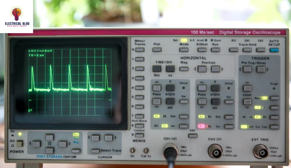
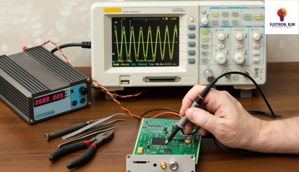
A cathode ray oscilloscope (CRO) is a fundamental tool in electronics, widely used in both modern and traditional laboratory settings. This powerful instrument helps engineers and researchers analyze electrical signals by plotting their variations over time. With a display that visually represents changes in voltage, the CRO is essential for testing and troubleshooting electronic circuits in various applications, from radio communication to TV receivers.
The oscilloscope works by capturing signals through probes and mapping them along the x-axis and y-axis, with amplitude indicating the strength of the signal. Its vertical and horizontal controllers allow precise adjustments, while triggers help stabilize the waveform for accurate readings. Whether in research, product design, or maintenance work, the CRO remains a cornerstone of signal diagnostics in the world of electronic measurement.
What is a cathode-ray oscilloscope?
A cathode ray oscilloscope is an electronic instrument designed to observe electrical signals over time. It captures input variations and displays them as a waveform, showing key properties like amplitude, frequency, and distortion. Originally called an oscillograph, it helps in test procedures by representing data on a graphed scale. The oscilloscope measures voltage, rise, and interval, ensuring precise signal analysis. Its ability to track ray behavior and signal changes makes it an essential tool in diagnostics.
Cathode ray oscilloscope diagram

The CRO consists of a CRT tube that generates an electron beam, which moves across a fluorescent screen to display signals. The beam is accelerated at high velocity and directed toward a focal point to create a visible spot. The oscilloscope operates with both high and low voltages, where the heater in the electron gun helps produce the electrons. A power supply circuit is provided to ensure the stable operation of all units within the device.
To control the beam, horizontal and vertical plates adjust its movement based on the input signal. The X-axis movement is managed by a time-dependent oscillator, while the vertical deflection is handled by an amplifier. A trigger circuit is used for synchronizing the time with the signal to ensure accurate detection. This setup allows the CRO to analyze varying waveforms efficiently.
The diagram of the oscilloscope includes a generator that helps maintain a steady signal display. The ray from the cathode moves across the screen like an electrical pencil, marking the waveform. The plates guide the electron beam, helping in detection and measurement. With proper control, the CRO provides accurate readings for diagnosing electrical circuits.
Working Principle
The CRO functions by controlling the movement of an electron ray using electrostatic forces. When the ray strikes the phosphor face, it creates a bright spot on the monitor. The oscilloscope applies electrical energy in two perpendicular directions, causing the spot to shift. These forces, acting mutually, help shape the waveform based on the input signal. This process ensures the necessary display for accurate measurement and analysis.
Construction of the Cathode Ray Oscilloscope
Cathode Ray Tube
Electronic Gun Assembly
Deflecting Plate
Fluorescent Screen for CRT
Glass Envelop
Cathode Ray Tube
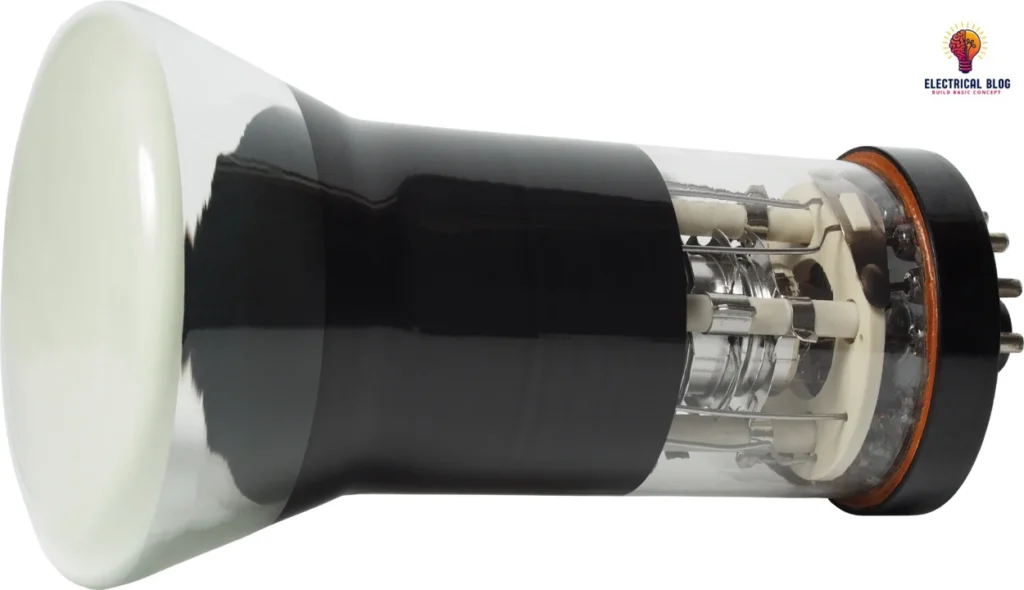
The Cathode Ray Tube (CRT) is a vacuum tube designed to display electronic signals visually. It contains an electron gun that generates a focused ray, which speeds toward the screen. The electrostatic plates control its movement, with the vertical plate moving it up and down, while the horizontal plate shifts it left and right. These beams are moved independently, making the CRO highly autonomous in signal positioning. The deflection system ensures accurate waveform display on the monitor for analysis.
Electronic Gun Assembly
The electron gun in a CRT tube emits electrons to form a ray, which is controlled for precise movement. A heater raises the temperature, helping the cathode release electrons efficiently. The grid and control electrodes regulate the flow, ensuring proper signal display.
The anodes, including pre-accelerating and accelerating, use high potential to speed up the electrons. These are connected to 1500 V, while the focusing electrodes are linked to 500 V. The ray is then directed toward the screen using electrostatic deflection plates.
To enhance precision, the oscilloscope uses electromagnetic and electrostatic focusing techniques. The coaxial cylinder and deposited layers of barium and strontium improve emission. This allows the ray to move smoothly along the vertical and horizontal axes.
Finally, the fluorescent lamp ensures a bright display, making signals easy to observe. The plates guide the ray, while supplies of power stabilize performance. The entire system is designed for moderate energy consumption and high accuracy.
Deflecting Plate
When the electron ray leaves the gun, it must pass through two sets of deflecting plates. The vertical plate, also called the Y plate, controls deflection up and down. The horizontal plate, known as the X plate, adjusts movement from left to right. These plates generate precise shifts, ensuring accurate signal representation on the screen. Otherwise, the display would be unclear and unreliable.
Fluorescent Screen of CRT
The CRT screen is designed to convert electrical energy into light when an electron ray hits its surface. The inner face of the faceplate is covered with a phosphor crystal, which plays a key role in this process. When struck, the phosphor undergoes crystallization, and the fluorescence occurrence generates a visible glow. The screen size is usually 100 mm × 100 mm, but for bigger displays, it may be slightly bent. The formation of the glass panel involves pressing molten material into shape and then heating it for durability.
Glass Envelope
The CRT has a conical glass envelope that is evacuated to allow smooth electron flow. The inside faces near the neck and display are covered with aquadag, a conducting material. This coating acts as a high-voltage electrode, which is connected electrically to the accelerating anode. This setup helps center the electron beam for accurate signal display.
Working of CRO
Vertical Deflection System
The vertical deflection system processes the input signals using an amplifier to amplify weak signals. The attenuator controls the signal strength before it is passed through multiple stages. Finally, the deflection plates adjust the amplified signal to produce the desired waveform for analysis.
Horizontal Deflection System
The horizontal deflection system controls how the input signals move across the screen. A sawtooth generator produces a steady voltage, which is amplified by horizontal amplifiers. The deflection plates are penetrated by this sweep signal, creating a time base. A trigger helps in synchronizing the movement for an accurate display. The selector switches adjust the position, allowing different types of sweeps to function properly in the circuit mechanism.
Recurrent Sweep
A new sweep is started immodestly after the end of the previous cycle, maintaining a respective sawtooth pattern.
Triggered Sweep
A triggered sweep is initiated only when the desired waveform is observed, ensuring accurate signal examination. This prevents the circuit from running inoperable, making it useful for unpredictable signals. The sweep starts at the right moment, avoiding unnecessary motion in the predicted display.
Non-Sawtooth Sweep
The non-sawtooth sweep helps to compare the frequency of two input voltages by measuring the difference between them.
Drive Sweep
A drive sweep operates in a free-running mode but is triggered by the signal under test for precise timing.
Synchronization
Synchronization ensures a stationary pattern by aligning the sweep with the signal using a selector to choose the right sources for accurate measurement.
Signal Measurement
The signal is measured using a vertical amplifier, while the trigger is abstained from the input for an accurate display.
External Trigger
An external trigger must be present to synchronize the signal with an external source for an accurate waveform display.
Line Trigger
A line trigger is produced by the power supply to stabilize the waveform display.
Intensity Modulation
Brightening of the display causes a signal to be produced by inserting it between the cathode and ground, achieving effective modulation.
Positioning Control
By applying a small internal voltage source through a potentiometer, the position of the signal can be controlled using direct connections to the detecting plates, maintaining independent control.
Intensity Control
The difference in intensity is set by changing the grid potential with respect to the cathode.
Electrical Quantities Measurements
Measurement of Amplitude
Measurement of Time Period
Measurement of Frequency
Measurement of Amplitude
The CRO can exhibit a stable signal over time, allowing the user to display the voltage in a clear way. By pressing a button at the top of the board, you can change the volt/division setting. This function modifies the number of partitions that cover the waveform, so you can easily acquire the correct amplitude reading. Using the formula:
A = j x nv
Where j is the value for each division, you measure the vertical scaling with no difficulty. These features keep the displays accurate for precise measurements.
Measurement of Time Period
The CRO displays a voltage signal on the screen as a function of time in the horizontal direction. By adjusting the knob on the panel, you can vary the divisions that cover one complete cycle of the periodic waveform. The duration can be determined using the formula:
T = k × nh
Where k is the value per division. The whole measurement process ensures accurate readings for any number of waveforms present.
Measurement of Frequency
The CRO is used to measure frequency by analyzing the waveform on the display. The horizontal scale helps in counting the partitions from start to finish as the signal crosses the reference line. To enhance accuracy, the area of the waveform can be expanded for better measurement.
The time period is determined using the division method, and frequency is signified mathematically as:
f = 1/T
This method allows for precise conversion of time into frequency for a clear analysis.
Controls of the Cathode Ray Oscilloscope
The CRO has several controls that help to adjust the waveform display.
Position
The position control moves the spot left or right, while the brightness control adjusts the intensity of the electron beam. The focus control sharpens the display by modifying the focal length of the lens.
Calibration circuit
The calibration circuit ensures accuracy by using an oscillator to generate a preset waveform. The time base generator is utilized to create a steady signal, which helps in synchronizing the oscilloscope display. The calibration function keeps measurements reliable by ensuring proper scaling.
Blanking system
The blanking system prevents unwanted traces on the screen by controlling the electron beam when it is not in use. The grids regulate the intensity, allowing adjustments to the power of the beam. The anode voltage is applied to maintain the beam’s movement.
Electrostatic system
The electrostatic system helps in directing the beam by using charged plates to control its path. The control handle makes it easier to fine-tune settings for a serious signal display. The beam can be adjusted based on the requirements of the oscilloscope.
Astigmatism
Other essential fundamental features include astigmatism correction, which ensures clear visuals without distortion. The CRO requires proper directing of signals for accurate readings. The present system allows efficient testing, making it a valuable tool in electronics.
Applications of CRO
The CRO is widely used in research laboratories and communication stations to monitor electrical signals and analyze waveforms. It helps in measuring voltage, current, frequency, and resistance, making it essential for testing circuits in AM and FM systems. Engineers use it to check the phase, inductance, and admittance of different components, while researchers use it to verify new designs and study hysteresis loops and BH curves.
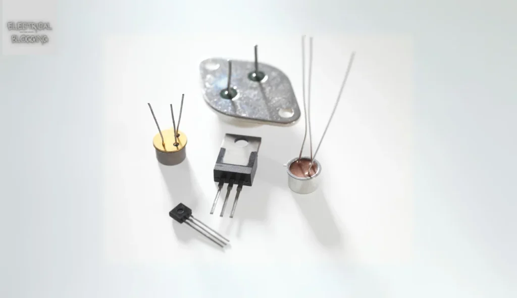
In the medical field, the Cathode Ray Oscilloscope helps track heartbeat reactions and analyze nervous system responses. It is also used in radar, TV, and engine pressure analysis. The resonance property of the device allows it to display the bandwidth and shape of signals. Additionally, it is valuable for observing and comparing transistor curves, making it useful in power and analog electronics applications.
Advantages of Cathode Ray Oscilloscope
The CRO is a highly efficient tool for waveform examination and voltage measurement, ensuring consistency and quality in results. It saves time by providing accurate frequency and phase measurements while maintaining regulatory compliance. Its hassle-free operation makes it ideal for problem-solving in various applications. The cost is reasonable, and minimal training requirements make it accessible for users with different levels of expertise and experience. With a strong capacity for diagnostics, it guarantees assurance in electrical testing while adhering to a structured timeline.
Disadvantages of Cathode Ray Oscilloscope
Although oscilloscopes provide accurate waveform analysis, they are expensive compared to multimeters and other measuring devices. They are complicated to repair if damaged and require complete isolation. The screen has multiple control terminals, making it difficult to understand at one time. Additionally, they are huge, heavy, and consume more power. For better clarity, ease of use, and multiple channel capture, many prefer the Digital Storage Oscilloscope.
Uses of Cathode Ray Oscilloscope
The Cathode Ray Oscilloscope is widely used in the laboratory to display waveforms and measure the potential difference. It also works as a voltmeter and helps analyze short time intervals in signals.
Conclusion
The Cathode Ray Oscilloscope (CRO) is an indispensable tool in electronic testing, offering precise measurements and high accuracy for waveform analysis. Its versatile nature makes it valuable for professionals, researchers, and educators, helping in the study of dynamic characteristics and time-area conduct in circuits. Despite challenges like impedance, maintenance requirements, and limited data transfer, the advantages of quick diagnosis and educational value far exceed these issues. The CRO’s significance in modern applications continues to grow, ensuring its continuous role in inspection and electrical signal analysis.


